Gleason will introduce several new machine technologies at IMTS ’08 booth #B-6902 that are designed to take cost out of bevel and cylindrical gear production:
• The GENESIS® Vertical Hobbing Machine, a member of Gleason’s revolutionary new family of gear production machines. The hobber is particularly well suited for dry machining and features a small, compact machine footprint while delivering long-sought productivity improvements for spur and helical gears with diameters up to 210mm in diameter.
• The GENESIS® Threaded Wheel Grinding Machine, ideal for high production environments where even seconds count. The fastest, most compact machine in its class, with all of the operating and maintenance advantages of the new Genesis platform.
• The P 600/800 G Profile Grinding Machine, equipped with a powerful new suite of profile grinding software, greatly reducing manual setup and other costly non-productive time.
• SIGMA 475 and 1500GMM Analytical Gear Testers, delivering the highest accuracy and flexibility for complete bevel and cylindrical gear inspection. They incorporate a new three dimensional scanning probe head. They’re also powered by new GAMA native Windows-based software, capable of covering a vast array of cylindrical and bevel gear applications.
• New cutting tools and workholding systems will be on display, including a comprehensive line of hobs, shaper cutters, bevel blades and heads, replatable CBN and diamond grinding and dressing wheels, and plated diamond rolls and milling cutters.
Gleason Corporation is a world leader in the development, manufacture, and sale of gear production machinery and related equipment. The company’s products are used by customers in automotive, truck, aircraft, agriculture, construction, power tool, and marine industries, and by a diverse set of customers serving various industrial equipment markets. Gleason has manufacturing operations in Rochester, New York; Rockford, Illinois; Dayton, Ohio; Plymouth, England; Munich and Ludwigsburg, Germany; Bangalore; India, Studen, Switzerland; and Suzhou, China. It has sales and service offices throughout the North and South America, Europe, and in the Asia-Pacific region.
More information is available by visiting [www.gleason.com].
The MAG Cincinnati FTV 5 vertical machining center meets IMTS searches for high productivity, versatility, and earnings capacity at five-axis machining. Heavy-duty fixed table/traveling column design—available in 1800 mm, 2500 mm and 3700 mm X-axis models—performs high-output cutting of a wide range of materials from aluminum to today’s hardest metals, particularly titanium alloys.
Precision five-axis/five-sided processing avoids refixturing and error-stacking, while reducing work-in-process. The high structural strength and stability of the FTV 5 machine base and fixed table accommodate loads of 6000, 8000 and 10,000 kg respectively without deformation effects on accuracy, while enabling pendulum loading to reduce load and unload time resulting in high in-cut productivity. Optional dual front load doors allow tables to be zoned with a center partition, permitting in-cycle loading to the open zone while the other is in-cut for near-continuous spindle utilization. The FTV 5 comes standard with high-performance HSK63A 27kW (35.2 hp) 18,000 rpm spindle with an HSK100 spindle optionally available. An FTV 5 2500 will be shown at MAG Industrial Automation Services booth #A-8218, the largest of any exhibitor at IMTS.
Versatile machine design allows FTV 5 machines to bring five-axis processing to everything from extremely large workpieces to multiple batch fixtured parts. The FTV 5 lowers machining time and cost for industries like aerospace, automotive, die & mold, heavy equipment, and power generation that produce large, complex geometry parts. Side doors aid loading of longer parts. Massive table capacity allows the FTV 5 to produce multiples of smaller contoured parts for specialty manufacturers and job shops or to perform flexible, mixed batch machining, while five-axis simultaneous interpolation allows simplified fixturing.
The contouring head provides up to ±45° A-axis tilt and full 360° C-axis rotation per second. Robust construction and high-performance design provide speed and power (swivel torque up to 1300 Nm) to contouring cuts. Brushless spindle torque motors eliminate conventional gearboxes, backlash and maintenance issues, while providing longer wear, faster rotary motion, high torque and high accuracy. Exceptional Z axis travel of 800 mm allows use of shorter tools and higher rpm, reducing vibration for better tool life and part finishes.
The traveling column rides on high-capacity, maintenance-free caged roller guide ways to provide all axis motion in delivering 40 m/min fast rapid and 20 m/min max. feed rate with ±3/4 µm positioning accuracy. Dynamically engineered with high strength to weight, the column configuration provides high Y-axis range of 1005 mm within a compact machine footprint. The machine configuration allows the operator to reach the table with ease and access the spindle while standing at floor level.
At IMTS 2008, Mitsubishi Heavy Industries of America, Inc., Machine Tool Division will be exhibiting in the North Hall Gear Pavilion, booth B-7025. On display will be a fully automated GE15A gear hobbing machine with pallet conveyor supplied by Creative Automation, Inc., of Ypsilanti, Michigan (booth B-6445). The GE15A is a highly flexible gear hobbing machine with a work piece capacity of 150mm diameter and 4 Module. The machine will be utilizing Mitsubishi SuperDry II cutting tools in an environmentally friendly, coolant free, high speed cutting process. Features that enhance the flexibility include quick-change pallet adapters and cutter arbors and an enhanced CNC operator screen with user-friendly graphics.
Also on display will be Mitsubishi’s model ZE15A generating type gear grinder. With its fully automatic eight-axis CNC control, ring type automatic loader, automatic dressing unit, automatic grinding wheel balancing unit, and direct drive motors, this machine has been designed for efficient high quality production. You are invited to visit Mitsubishi and find a gear machine in their extensive inventory that meets your immediate needs.
The Timken Company has released its Bearing Selection Guide Version 3.0 for users including original equipment manufacturers, distributors, students, and engineers. The new electronic guide contains engineering calculations and a database of more than 5,000 bearings including tapered, spherical, cylindrical, and needle roller bearings, as well as ball bearings.
The software program is an interactive tool that enables users to select the most appropriate Timken® bearings for a given application. The program provides users with a reliable, easy-to-use method for building an application model and selecting the right bearings to satisfy specific dimension and performance requirements. The new version offers improvements to previously available functions including engineering calculations, search capabilities and average bearing life predictions. Additionally, designers are able to share the applications created with a local Timken representative or authorized distributor for further discussion on alternative scenarios and selection recommendations. The program, which is compatible with a number of Microsoft Windows platforms, is available in English, French, German, Italian, Spanish, and Chinese. To assist users, bearing selection scenarios and a detailed user manual are available. “This new guide is designed to simplify the bearing selection process for customers. It’s also an alternative to using hardcopy catalogs when searching for bearings,” says Ravi Bhatia, Timken’s vice president of engineering and integration. “For many of our customers, this new tool can lead to reduced engineering time, better designs and an improved performance.”
The Timken Company keeps the world turning, with innovative friction management and power transmission products and services that enable customers to perform faster and more smoothly and efficiently. With sales of $5.2 billion in 2007, operations in 27 countries, and approximately 25,000 employees, Timken is Where You Turn™ for better performance.
To learn more visit the engineers’ section of the Knowledge Center at [www.timken.com].
Riverside Spline & Gear, Inc., announces the installation of a VTL-1000 CNC vertical turning lathe manufactured by the You Ji Machine Industrial Co., LTD, which allows for larger turning up to 43 inches. Earlier this year the company installed its second Nexus 350 turning center, which was its fifth CNC lathe purchase from Mazak.
“We have seen an increase in larger gears due to our acquisition of a Hofler 900 gear grinder,” according to Aaron Forest, vice president of operations. “The purchase of the You Ji VTL-1000 is in response to that demand, allowing all of our turning to be done in house.”
The Versa-Mate, a compact vertical broaching machine, utilizes cutting edge servo-motor and planetary roller screw technology yet relies on traditional “slide and way” construction resulting in a rugged, heavy-duty machine that stands up to the most demanding production environments. The Versa-Mate’s electromechanical drive system offers numerous advantages compared to hydraulically powered machines, including:
•No hydraulic unit = less floor space required •No hydraulic unit = no leaks and less maintenance •No hydraulic oil = no need to purchase or dispose of hydraulic oil •Drive motor runs only on demand = lower energy costs •Smoother cutting action = better part finish and tool life
The unique design of this machine allows it to be adapted for either internal or surface broaching applications, resulting in valuable in-field versatility and utility. The Versa-Mate can be tooled for multiple station operation and is easily automated, which allows the user to maximize their broach production. See the Versa-Mate in operation at BMS booth #B-7220, North Hall, IMTS 2008, September 8-13 in Chicago.
FANUC Robotics America, Inc., recently introduced its M-710iC/50 SE FoundryPRO robot, IP67 protected for operation in the harshest environments. The entire robot is coated with a special epoxy, and the wrist has protective covers to withstand high-pressure washing. In addition, the base of the robot purges air to avoid vapor entrance.
“The M-710iC/50 SE sets the benchmark for robots working in the super-harsh environments of die casting and foundry facilities,” says Virgil Wilson, product manager. “In addition to the protective epoxy and air purge, we’ve incorporated coated bolts and double oil seals at the joints, making this a truly waterproof robot.”
The six-axis M-710iC/50 SE is the latest member of the M-710iC robot series, which offers payloads ranging from 20 kg to 70 kg, and a reach of 1360 mm to 3110 mm. Multiple mounting methods—including floor, ceiling, angle, and wall—make it possible for users to have better access to unusual work pieces.
“This is an exciting robot based on its capabilities and flexibility,” Wilson adds. “It’s rated ‘best in class’ for speed and has one of the largest work envelopes in its class. In addition, its compact size and ability to flip over and work behind itself maximizes flexibility for work cell design and saves valuable floor space.”
FANUC Robotics America designs, engineers, and manufactures industrial robots and robotic systems for a wide range of applications including arc and spot welding, material handling (machine tending, picking, packing, palletizing), material removal, assembly, paint finishing, and dispensing. The company also provides application-specific software, controls, vision products, and complete support services. After 26 years of success, FANUC Robotics maintains its position as the leading robotics company in the Americas. A subsidiary of FANUC LTD in Japan, the company is headquartered in Detroit and has facilities in Chicago; Los Angeles; Charlotte, North Carolina; Cincinnati and Toledo, Ohio; Toronto; Montreal; Aguascalientes, Mexico; and Sao Paulo, Brazil. Over 200,000 FANUC robots are installed worldwide.
For more information call (800) iQ-ROBOT, option 5, or go to [www.fanucrobotics.com].
Extending quenchant life and improving heat treating quality will be the focus of a two-day conference on Quenching and Control of Distortion in Heat Treated Gears. Sponsored by the ASM Heat Treating Society, the event will be held Sept. 24-25 at the Radisson Hotel at Milwaukee Airport.
The program was organized by Scott MacKenzie, Houghton International; Dave Guisbert, QA Metallurgical Services LLC; Cynthia Barnicki, Milwaukee School of Engineering; and Dennis Beauchesne, ECM USA, Inc. “Our program starts with the basics of selection, care, and maintenance—the dos and donts,” MacKenzie says. “From there we’ll also cover new methods for effective recovery, control, specialized techniques, and safety and longevity concerns.”
Topics include Chemistry of Quenching, Care and Maintenance of Quenchants (Oil and Polymer), Quality Assurance and Monitoring of Quenching Systems, Application of Quench Presses to Control Gear Distortion, Use of FEA to Predict Distortion and Microstructure, and Metallurgical Factors Affecting Distortion of Heat Treated Gears. A panel discussion—Use and Control of Polymer Quenchants—Selection, Maintenance and Control—will provide additional opportunities to discuss problems and solutions with heat treating and quenching experts. A one-day course, Heat Treating for the Non-Heat Treater, will be held immediately prior to the conference on Sept. 23 to provide added coverage of heat treating basics.
ASM Heat Treating Society reflects the composition of the worldwide heat treating community and includes captive and commercial heat treaters, equipment manufacturers, researchers, governments and technicians.
Makino’s MAG series of five-axis horizontal machining centers are specifically suited to meet the just-in-time manufacturing needs of the aerospace industry. The newest offering in this series is the MAG1, a five-axis machining center designed to handle quick, high precision aluminum production of parts up to 1500 mm. See this and other new technologies in Makino’s booths A-8301 and D-4101 (EDM) at IMTS in Chicago Sept. 8-12, 2008.
The MAG1 is positioned to produce structural parts such as ribs, leading edges, and trailing edges of aircraft wing structures. The X-, Y-, and Z-axis travels of 1520 mm x 1100 mm x 1350 mm allow for part sizes up to 1500 mm x 1500 mm and 1300 kg. The MAG1’s construction features a three-point support system that eliminates leveling maintenance and reduces the cost of installation, and a 60-position automatic tool changer (up to 120 available), allowing continuous, uninterrupted machining.
The machine is equipped with a 33,000-RPM, 107 HP HSK80 spindle designed to easily access deep pockets that most other machines cannot reach. The A-axis rotates between +100 degrees and -110 degrees to provide full five-axis roughing and finishing. Makino’s patented spindle cooling technology is also included to ensure longer spindle life during extended machining times. The B-axis resides on the machine side (NCRT), allowing the spindle to access the front and rear of the part and allows for four-sided fixture strategies.
The MAG1 also features Super Geometric Intelligence v.4 (SGI.4) control technology to allow for high feed machining without losing accuracy, and monitoring software for users to keep constant watch on bearing temperature and vibration during cutting. The standard coolant system includes spindle head and terrace washing, ceiling showers, and table washing, which enable the MAG1 to maintain part accuracies during long machining periods. A center trough chip removal system assists high metal removal operation. The automatic pallet transfer and storage system of the MAG1 integrates with Makino’s MMC2 system. Makino’s Continuous Pressure Hydraulics (CPH) system is also included to interface with hydraulic fixtures. For part sizes beyond 1500mm, Makino offers the MAG3 and MAG7.
Makino is a global provider of advanced machining technology and application support for the metalcutting and die/mold industries, dedicated to driving out more costs from your manufacturing operation than any other competitive machine tool manufacturer. Makino manufacturing and service centers are located in the United States, Japan, Germany, Singapore, Italy, France, Korea, Taiwan, Turkey, China, Mexico, Brazil, and India, and are supported by a worldwide distributor network.
For more information call (800) 552-3288 or go to [www.makino.com].
Working together, EZ-Lift material handling magnets and MagVISE magnetic workholding systems are proven to reduce setup and part changeover times by 50 percent or more compared to traditional material handling and workholding methods, including clamps and vises. Thousands of customers use its magnetic products to lift, move, and hold their material more quickly and efficiently than ever before.
For workholding Earth-Chain offers EEPM electro-permanent magnetic chucks and ECB permanent magnetic vises (shown in photo). Both solutions provide fast, powerful workholding with tons of holding power and can be customized to suit your application with induction blocks, subplates, and work stops as needed. EZ-Lift material handling magnets have the highest built-in safety factor in the industry—3.5 times capacity, and they are rated to lift up to 6,600 lbs. They come in six sizes and have dozens of uses around the shop.
Sunnen’s new SV-310 vertical CNC honing system combines multi-spindle machine configurations with wide tooling choices and 762mm/30" stroke for bore sizing of small and medium-sized gas/diesel engine blocks, large gears, air compressors, aerospace parts, refrigeration compressors, and similar small or large multi-bore parts. A work envelope of 1016mm x 1778mm/40" x 70" and weight capacity up to 909 kg/2000 lb provide versatility for processing a wide range parts. An optional tool-guide assembly and variety of bore-diameter gaging systems combine with a servo-controlled X-axis travel of 1143mm/45" to allow automated honing of multi-bore blocks with high precision. Straightness sensing capability provides a display of the bore profile during the cycle. Combined with a patented, servo stroking system, it allows the SV-310 to auto-dwell in any part of the bore to correct straightness automatically in the shortest cycle time. The SV-310 can be used to hone parts with inside diameters from 19-200 mm (0.75-8.00"), depending on the tool options selected.
Designed from the ground up for automated processing of mid to high part volumes, the SV-310 features full-height access doors and enclosure preconfigured for use with robotic part loading systems, while the CNC control includes a built-in automation interface. A 20-amp power supply and multiple E-stop contacts add versatility and allow convenient automation control. Setup is simplified with a three-axis hand wheel for fine-tuning X-axis position, vertical stroke, and tool feed. The Windows-based, color, touch-screen control features multi-language capability, pull-down menus, unlimited capacity for job setups, and programmable custom tools. In addition to optional in-process air gaging, a variety of optional post-process air-gage systems can integrate with the control for SPC data collection, as well as automatic compensation of size, taper, and straightness. The control allows easy programming of multiple bore positions.
The SV-310 is built on a malleable iron base for rigidity and vibration damping. The machine’s servo-controlled, straight-line stroke motion is driven by a ballscrew at rates of 1-160 strokes per minute, while a powerful 5.5 kW/7.5 hp spindle provides ample torque for fast metal removal with tools outfitted with metal-bond cubic boron nitride and diamond abrasives or standard aluminum oxide and silicon carbide stones. Oversized, lubed-for-life guide ways for horizontal and vertical axes provide smooth operation and long, maintenance-free life. An optional T-slot table 800 x 1545 x 45.5 mm can be mounted on the casting base, along with an elevated fixture frame for holding all types of fixtures.
The SV-310 can be equipped with a wide range of Sunnen tooling, such as the new PH precision multi-stone tool. The PH tool can hold as many as 12 stones for optimum straightness and roundness on bores 3.00-7.5"/76.2-190.5mm, while delivering high efficiency in mid- and high-volume production. It is available in single or two-stage configurations, along with optional, integral air-gaging for in-process monitoring.
For additional information visit Sunnen’s IMTS booth #B-7200. Also call (800) 325-3670, send e-mail to sales@sunnen.com, or go to [www.sunnen.com].
Precision deburring of metal parts at speeds up to 480 pieces per hour will be demonstrated by ALMCO, Inc., at IMTS booth #6846 with a unique, automated, double-spindle finishing machine. The world’s only manufacturer of such equipment, ALMCO has designed the robot-adaptable machine, Model 2SF-48RA, to handle complex pieces with up to 16-inch diameters and deliver exceptionally close-tolerance radiuses. The 48 inch-diameter tub filled with finishing abrasive receives parts from two spindles, on opposite sides of the tub, which automatically raise the parts from the abrasive after a specified period of time. The abrasive is spun by centrifugal force into what the company refers to as a “form-fitting grinding wheel.” The unique process assures uniform deburring and finishing of all part surfaces, exactly to user specifications that often cannot be achieved by conventional mechanical finishing methods.
The 2SF-48RA is ideally suited to the deburring of complex parts such as gears, bearing cages, splined shafts, pump rotors, and jet compressor discs and blades. The machine requires minimal floor space of approximately 5 feet by 8 feet. A key component for 100-precent automation when robots are added is the unit’s programmer that interacts with parts feed/load/unload operations and time-cycle sequencing. The spindle machine also features a constant spray of liquid compound and water for continuous cleaning of parts.
A second, manually operated spindle finisher—the compact S2-30—and other finishing units and parts washer/dryers representing the company’s broad line of equipment will also be demonstrated in the ALMCO booth. Additionally, a Spraymaster front-load cabinet washer carrying the KleenTec nameplate will show the recent marriage of ALMCO and its sister company under the ALMCO KleenTec corporate name.
You’ve been with the company for five years now, how did you come to join it?”
I was originally trained as an engineer, and I was working with a company in an unrelated field that required a great deal of traveling—and this was right when I’d gotten married, too, so being on the road so much was starting to become a problem. A lot of the work was based out of the West Coast, so I was interested in finding something in Illinois, where I’m from. When I found out about an engineering position with Clifford-Jacobs I was very interested—I liked the people I’d met, the positive atmosphere, and the company’s great reputation, too—and when they offered me the job I accepted it immediately. It was a great opportunity, and I definitely made the right decision by taking advantage of it.
You began in engineering but you’re now sales manager… how did that come about?
It was really a natural transition, if you think about it. When I first started the job I was doing straight design work, and then it made sense for me to get involved in actually quoting the customer. I found that my engineering background and understanding of products and processes at that level not only allowed me to “speak the language” the customer was accustomed to, but it also helped gain their confidence since they knew I had hands-on experience with what we were talking about. As I got more involved in that aspect of the business—collaborating with our customers on quotes for the products and services they needed—I came into more and more contact with Justin McCarthy, who was vice president of sales and marketing for Clifford-Jacobs at the time. We began working pretty closely together, and it was a real pleasure for me to be able to learn about sales from such a professional.
Then, when he left to become executive vice president of sales and marketing for Ajax Rolled Ring and Machine, Inc., David Sulzbach—who is president of Clifford-Jacobs—asked if I’d be interested in stepping up to the position of sales manager in Justin’s absence. Again, it was another great opportunity, and I felt that the time I’d spent working alongside Justin had prepared me for the role, so I was honored to accept the promotion to sales manager. How have you approached your new responsibilities?
The good thing is that I already knew the vast majority of our customers, but I’ve made a point of reaching out to everyone so they’ll be comfortable with the transition. I want them to know there will be no change in the level of customer service they’ve come to expect from us. At the same time, I need to hear from them about areas where we could improve what we’re doing, because when we say we want to develop “partnerships of value” with our customers, we really mean it. So the first thing I was interested in doing was learning as much about our existing customers as I possibly could, which often includes making site visits to familiarize myself with their operation, and to support David Sulzback in his efforts to help position the company as it grows and moves forward. Part of that involves constantly considering new markets to pursue in addition to those we currently serve, which includes off-highway/construction equipment, mining, forestry, oilfield, defense, power generation, railway, and aerospace equipment, among others. But we also need to think about our presence from a geographic standpoint, including emerging markets found overseas.
As to how we accomplish this, one of my responsibilities includes overseeing the efforts of our extensive network of sales representatives, numbering more than 20 individuals who are found across the United States and Canada. I’m here to follow up on any leads they may generate, and also to accompany them to visit current or potential customers to see how we can meet their requirements. We work with some very high-profile, Fortune 500 companies—Timken, Caterpillar, National Oilwell Varco, and Boeing Aerospace, for example—and we’re constantly working to live up to their expectations and confidence in us by acquiring the latest equipment and technologies. We’ve invested more than $7 million in capital improvements in recent years, in fact. So no matter the size of the order, or the complexity or material grade of the part, we’re eager to work with our customers on their custom forgings. Because if we help them meet their goals, then we’ve reached our own goal as well.
Do you put safety first in your workplace? Are you a safety conscious person… and I mean really safety conscious? I don’t know anyone who’s not in favor of safety, but I know very few people who actually put safety first. We don’t really consider safety before production, for instance, nor do we really consider safety before costs.
We don’t really consider safety before quality, and we don’t even consider safety before we hire someone or purchase a new piece of equipment. So, is “safety first” a viable consideration? Well, let’s consider what we mean when we speak the words. Most of us merely state the phrase with the same conviction we say other things, such as “money isn’t everything” or “cleanliness is next to godliness.” In other words, it’s something we’re supposed to believe in, so we pay it lip service without the slightest intention of truly making it a priority. Safety seems to pretty much be an afterthought these days, and I believe that we as a society are worse off because of it.
“Safety first” means just that: Before we commit to any course of action in our lives, it behooves us to consider the possible hazards associated with the intended course of action. How do we promote this attitude in ourselves, and also in those we have influence over? I have a few suggestions. Each day as you sit down at your desk, or approach your machine or workstation, take a pad of paper with you and label the first page “Safety Suggestions” at the top. Then, write the number one on the first line. Leave it blank for a moment and consider what the first thing is that you’re about to do. As you consider the first order of business ask yourself if there isn’t a way the task could be accomplished more safely. The answer doesn’t have to be groundbreaking revelation. It may be as simple as “I’d better put oil dry on that spot on the floor,” or “Maybe I should recommend better hearing protection with this new machine,” or “I should remember to wear my safety glasses when I’m in the shop.” Whatever your thought is, write it down on the first line. Now number the second line, and if you come up with another safe thought, write it down. Keep doing this throughout the day; trying to dream up safer ways of approaching your activities, and then writing them down. The next morning, do the same thing, but make an attempt to write down more safety-related thoughts than you did the day before. In other words, see if you can increase the number of entries you make each day. While this procedure may seem awkward at first, you will be amazed by how many quick little things you can do that will make your time spent on the job simpler, and safer. One result of this exercise is that you will have compiled a written record of safety tips that everyone on your shop floor can utilize. The best result, of course—besides increased safety—is that you’ll finally be able to say that yes, you are actually putting safety first.
One topic covered in this issue of the magazine is ongoing equipment maintenance. While this procedure contributes to workplace safety in and of itself, how much thought goes into the safety of the employees who are actually performing the maintenance? Does your company require the use of a lockout/tagout procedure? Are your maintenance personnel equipped with the proper tools to perform the required maintenance? Are the tools used maintained properly? All of these factors must be addressed before you can be sure the work is being done in the safest possible manner. One factor that doesn’t seem to be considered very often is the training of the maintenance personnel. In my business I constantly work with various maintenance personnel, and I find that they usually have a minimal amount of training on the equipment they’re expected to keep running properly. I find this to be a very haphazard method of maintaining machinery of any kind, and I would suggest that each employer make a concentrated effort to give these technicians all the training they need. After all, anything they overlook as a result of lacking proper training can be very costly, but more than anything it can be dangerous.
Oil cleanliness is essential for gear unit reliability. To achieve this cleanliness in force-feed lubrication systems filters should be the last piece of equipment prior to the lubricant entering the housing. All filters should have a minimum efficiency of 90 percent at the specified micron rating. The life of bearings and gears increase with improved oil filtration, but industry standard calculation methods do not take this into consideration and are somewhat lax in specifying a micron rating. R. Bachu, at the Imperial College of London, in 1981 conducted rolling bearing tests. S.H. Lowenthal conducted similar independent tests and published papers in 1978, 1979, 1980, and 1982. Following the tests it was possible to calculate life adjustment factors for the effects of oil filtration. In the London tests a gear test machine was used to generate gear debris from helicopter gear units. The gear oil was passed through one to four filters from 1 μm to 40 μm. As was expected, the lower the filtration the less the wear. What was not expected was the rate of wear with relatively fine filtration. Particles had to be less than 3 μm to have no effect on wear. However, if the 40 μm filter was used for just 30 minutes then replaced with a 3 μm filter, the bearing life was the same as if the whole test had been conducted with a 40 μm filter, indicating the damage was immediate and permanent. The predicted life with a 40 μm is reduced by a fifth.
The contacting surfaces are worn by the number and size of the particles. A laboratory procedure known as the “Multi Pass Test” is used to evaluate the efficiency of lubrication filters. In this century laser particle counters enable an accurate count of particles as small as 0.7 μm. A slurry of contaminants are slowly fed into a recirculating loop that contains the filter being tested. The test commences with a clean filter and is completed when a terminal differential pressure is reached. Fluid samples are continuously taken upstream and downstream of the filter and directed into automatic particle counters. The results are averaged over the filter life from clean to terminal and recorded as a ratio of upstream to downstream particles. The AGMA standard #9005-D94 for industrial gear lubrication advises that pressure lubrication systems should have a filter on the pressure side and in the absence of a specific manufacturers recommendation the filter should be no coarser than 50 μm with ball or roller bearings and 25 μm with journal bearings. The API standard #677 “Units for Refinery Service” required full-flow filters with replaceable elements 25 μm or finer for babbited bearings and 10 μm or finer for aluminum or microbabbited bearings. Micron particle size indicates the shape and size of a spherical bead. For example, with the element’s maximum pressure drop, 10 microns implies that the efficiency of the filter on particles that are 10 microns or larger in diameter will be no less than 90 percent for the life of the element. For the optimum life of a typical hydrodynamic bearing the filter should maintain a cleanliness level of ISO Code 18/14. In other words, 2,000 particles under IS micron sizes, and 100 particles over IS microns is desirable.
The filter cartridge materials should be water and corrosion resistant. Their limit on operating temperature is set by API at 160ºF. A filtration level of 25 μm or finer nominal particle size is generally acceptable. Finer lubrication is definitely required with the lighter turbine oils and higher operating temperatures. ISO 4406:1999 provides a good guide to an oil cleanliness specification with 17/15/12 recommended for high performance gear units. Many of the large bulk users insist on a 10 μm filter being used between the tanker truck and their reservoir. They are also wise in obtaining an analysis of the loading sample and compare with a sample taken at unloading. If contaminants > 1.0ppm are discovered then other properties such as air release, foaming, and emulsion must be checked. Part I of this column, on seals, appeared in the July issue of Gear Solutions magazine.
The contact on single enveloping worm gear drives is the line contact. The changing form of the worm across the face of the gear makes it impossible to derive a simple mathematical expression for the contact curvature. In addition, the combination of the lead angle of the worm and position of the pitch plane of the worm in reference to the worm thread profile has predominant influence on the position and form of the actual contact line. The author here presents a report on the relative curvature of the worm and wheel at sections parallel to the axial section of a worm.
Curvature & Radius of Curvature
A curve is the locus of a point whose position vector r relative to a fixed origin may be expressed as a function of a single variable parameter. It is usually convenient to choose as the scalar parameter the length s of the arc of the curve measured from a fixed point A. Let P, Q be the points on the curve whose position vectors are r, r + δr corresponding to values s, s + δs of the parameter then δr is the vector PQ. The quotient ( δr / δs ) is a vector in the same direction as δr and in the limit, as δs tends to zero, this direction becomes that of the tangent at P. Moreover, the ratio of the lengths of chord PQ and the arc PQ tends to unify as Q moves up to coincide with P. Therefore, the limiting value of (δr / δs) is a unit vector parallel to tangent to the curve at P and in the positive direction (see Figure 1). If it is designated by t, then:
t = Lt. ( δr / δs )
δs→0
The curvature of the curve at any point is the arc rate of rotation of the tangent. Thus, if δθ is the angle between tangents at P & Q, δθ / δs is the average curvature of the arc PQ, and its limiting value as δs tends to zero is the curvature at the point P. This is sometimes called the first curvature of circular curvature. We shall denote it by κ.
Thus, κ = Lt. ( δθ / δs ) = d θ / d s = θ’ = 1 / ρ δs→0
ρ is called radius of circular curvature. The relative curvature of the surfaces in contact will be
1 / ρ = 1 / ρ1 + 1 / ρ2
A negative sign will be attached with the radius (ρ1 or ρ2 ) which is concave.
Tooth Profiles & Geometrical Relations
For general industrial purposes, helicoid sections for worm and wheel are mostly involute helicoids and screw helicoids. Both of these helicoids can be generated with a straight line generatrix, therefore their tooth geometry is simpler. Involute helicoids may be generated either by hobbing or by lathe (see Figure 2). When it is generated by lathe, half of the cutter included angle must be equal to the lead angle of base helix. From the properties of the involute helicoids, it is known that the teeth flank will have some curvature in its transverse section and the radius of curvature at pitch point will be given by:
ρ = Rp Sin αs (1)
A normal section of the curvature will have a radius of curvature:
ρn = Rp ( Sin ψn Cos2ψ ) = Rp ( Sin αn / Cos2 ( 90 –γ ) ) = Rp ( Sin αn Sin2 γ ) (2)
The radius of curvature at axial section is related with the radius of curvature at normal section according to the following equation:
1/ ρA = (1/Cos γ )* ( Cos αa / Cos αn )3 [( 1 / ρn ) + ( Sin2 γ / Rp ) * Sin αn * ( 1+ Cos2 αn )] (3)
By putting the value of ρn from equation (2) in the equation (3) and simplifying it, the following equation is obtained:
1/ ρA = ( Sin2 γ / Rp ) * [( 1 / Sin2αn ) + Sin αn * ( 1+ Cos2 αn )]
* (1 / Cos γ )* ( Cos αa / Cos αn )3 (4)
The radius of curvature at the axial section of the involute worm is obtained. The radius of curvature at axial section of screw helicoids is independent of its axial pressure angles, lead angle, and pitch diameter of the worm or wheel. Here curvature is a constant and is equal to zero.
Curvature Radius at a Section Parallel to Axial Section
The radius of curvature of the worm tooth flank at a point P is to be determined [2]. We follow Cartesian coordinate system, in which the central point of the transverse section of the worm is the origin (see Figure 3).
The worm axis represents Z axis, and the X & Y axis are as shown in the transverse section of worm. The coordinate of any point P on the helicoids (flank) will be the function of x, y & z. But for any section parallel to axial section, the value of y will be constant. Therefore, for a particular point P, z is the function of x only. From the definition of the pressure angle at any section it is known that:
Tan α = ∂Z /∂X
Or ( 1 / Cos2 α ) = 1+ (∂Z / ∂X )2
The point P in xx section may be indicated either by Cartesian coordinate system x, y, and z or by the polar coordinate β, r, z, so it is given that:
r2 = x2 + y2 and Tan β = y/x
In the worm axial section AA, Ya = 0, Xa = r and za being a function of r is given by za = f ( r )
Therefore, Tan αa = ( ∂ f ( r) / ∂ r ) ; 1/ ρa = – Cos3 αa = ( ∂2 f ( r) / ∂ r2 )
The equation to the helicoids plane is:
z = f ( r ) – ( β L / 2π )
Therefore, in section xx, Tan α = ( ∂ z / ∂ x )
= ( ∂ f ( r) / ∂ r ) (∂ r / ∂ x) – ( ∂ β / ∂ x ) ( L / 2 π )
= ( ∂ f ( r) / ∂ r ) ( x / r ) – ( L / 2 π ) ( y / (x2 + y2))
= Tan αa Cos β + Tan γ Sin β (5)
1/ ρ1 = – [Cos3α ( ∂ z / ∂ x )]
= – Cos3α [(∂2 f ( r) / ∂ r2)(∂ r / ∂ x)2)+( ∂ f ( r) / ∂ r )(∂2 r / ∂ x2) – ( ∂2 β / ∂ x2) (L /2 π )]
It is to be noted that for the present coordinate system ρ2 is positive when wheel flank is convex. ρ1 is positive when worm flank is concave [2].
Example 1
To calculate the relative curvature of an involute helicoid worm at a section which is parallel to axial section, the point of contact is assumed to make an angle approximately 20 degree with vertical plane. The worm have following gear parameters:
(Axial) Module ma=5, No. of start of worm Z1 = 1 diametrical quotient q = 10. Root diameter droot = 38.20 mm. Pitch circle diameter do = 50mm. Addendum diameter da = 60 mm, lead angle (at pitch circle diameter ) γo = 5.71059o. Normal pressure angle ( at pitch circle diameter ) n = 20o. Working center distance a’ = 125mm. Wheel teeth number Z2 = 40. Transmission ratio i = 40.
Solution: The exact coordinate point of contact in this case will be β = 20.762, r = 26.28 mm. (see ref. 3 ). The geometrical relations for involute helicoids worm gear is given as:
Tan2 γg = Tan2 αt = Tan2αao + Tan2 γo….(i)
Tan αao = Tan αno / Cos γo……………..(ii)
From equation (ii) αao = 20.09179 degree. Here, Rp = 25 mm
From equation (i) αt = 20.767152 degree
Substituting the values in equation (4) ρa = 273.80396 mm
From equation (5)
Tan α = Tan 20.09179 Cos 20.762 ÷ Tan 5.71059 Sin 20.762
= 0.3774808
α = 20.6806o
From equation (6) ρ1 = 278.91121 mm
From equation (8) a = 0.4559783 mm
From equation (7) ρ = 35.88828 mm
Example 2
To calculate the relative curvature of a screw helicoids worm at a section which is parallel to axial section. The point of contact is assumed to make an angle 20 degree with vertical plane. The worm of wheel have the same gear parameters as in example 1 except instead of normal pressure angle, axial pressure angle
( at p.c.d.) = 20 degree.
Solution: The contact position remains almost same for all types of worm and wheel which has got straight line generatrix (see note * at end). Therefore, here also it may be taken as:
β = 20.26 degree, r = 26.28 mm
At any position in axial section of screw helicoids 1 / ρa = 0
From equation (6) 1/ ρ1= 0.00070569 ,ρ1 = 1417.05 mm
a = 0.4559783 mm
From equation (7) ρ = 35.79487 mm
Example 3
For the gear pair of example 1 calculate the relative curvature at a section parallel to vertical plane making an angle approximately equal to 30 degrees.
Solution: The exact point of contact in this case will be at β = -28.155 degree, r = 28.35. The negative sign attached with indicates angle is at opposite side of assumed direction. So it can be dropped.
From equation (4) 1 / ρa = 0.00365224 ρa=273.80396 mm
From equation (5) α = 20.2888 degree
From equation (6) 1 / ρ1 = 0.00325236 ρ1= 307.46823 mm
a = 0.00484252 mm.
From equation (7) ρ = 34.679834 mm.
Example 4
For the gear pair of example 2 calculate relative curvature at a section parallel to vertical plane, making an angle of 30 degrees.
Solution: β = 28.1o, r ≈ 28.3 mm α = 20.2888 degree
From equation (6) 1/ρ = 0.000068584, ρ = 14580.64 mm
From equation (7) ρ = 34.665665 mm.
Example 5
For the gear pair of example 1 calculate relative curvature exactly at axial section.
Solution : Calculated ρa = 273.80396 mm, β = 0 degree,
r = 25 mm = Rp
α = αa = 20.09179 degree, a = 0
= ro2 Sin 20.09179o
ρ = 100 Sin 20.09179o
= 34.3525 mm
Example 6
For gear pair of example 2, calculate relative curvature exactly at axial section
Solution: Here t = ro2 Sin αa = 100 Sin 20o = 34.220 mm
Conclusions
Results show that the difference in relative curvature is more prominent toward the axial plane. As shifted from the axial plane, the difference in relative curvature between screw helicoids and involute helicoids goes on reducing.
It is noticed that the amount of relative curvature at a particular section is more in involute helicoids than the screw helicoid. In terms of only Hertzian contact stress (ignoring other factors like effect of contact ratio), involue helicoids should have better strength.
References
1) Niemann G. Machinen Elemente-Entwerfn. Berechnen und Gestalten im Maschinenbau-ZweiterBand, Springer Verlag, (1965)
2) Karl Kutzbach and Niemann G. Schnecken triebemit flussiger Reibung VDI-Forsch-Heft 412
3) Buckingham E. Analytical Mechanics of Gears. Dover Publications Inc. (1963)
4) Merrit H.E. Gear Engineering. A.H. Wheeler & Co Pvt. Ltd. (1984)
* “A comparison of figures shown a very close agreement between the forms and positions of the projections of the contact lines of the screw helicoids and the involute helicoids on the end sections of the worms, particularly those portions of them which lie on the thread sections of worms. Therefore, except for critical drives, which should always be analysed in detail, the conditions on either type of helicoids may be used as a very close approximation to those on any other type of helicoids with a straight line generatrix”—Buckingham.
The theory and practice of gear design is rich with examples of successful and sometimes outstanding combinations of various mathematical, manufacturing, and methodological approaches to the choice of the best parameters, defining the gear itself, its generating tools, and processes of generation and meshing of tooth flanks [1, 2, 3, and others]. Knowledge of involute spur and helical gears can be considered to be almost complete compared with other types of gears, and they also apply different approaches to the optimal (or rational) choice of their geometrical parameters.
This paper proposes a new approach—Advanced Gear Design (AGD)—on the basis of two reputed approaches, one of which is known as Direct Gear Design? (DGD) [4, 5, 6] and the other can be named as the Method of Dynamic Blocking Contours (DBC) [7, 8, 9]. The proposed approach uses the advantages of the first two in order to obtain the best decision when designing involute spur and helical gears.
Fig. 1: Tooth profile (the fillet portion is red); a, external geartooth; b, internal gear tooth; da, tooth tip circle diameter; db, base circle diameter; d, reference circle diameter; S, circular tooth thickness at the reference diameter; ν, involute intersection profile angle.
1: What We Imply By Optimal Design
We are going to consider two tasks that are typical for the optimal design of any product, including a gear:
• Optimizing the design, implying the choice of the best design decision according to the given criterion or a group of criteria;
• Optimizing the process of design, implying the increase of its productivity and quality.
The proposed concept of the first task solution means the rejection of the traditional approach to the design of involute spur and helical gears, where the first step is the assignment of parameters (as a rule, standard ones) of the initial generating tool (generating rack). Such an approach is justified in many practical cases from the manufacturing point of view, but it has restrictions, imposed both on the number of gear parameters and on the choice of the optimal decision. In the proposed approach the tool parameters are secondary and are determined after the gear parameters are chosen according to the given quality criteria with account of possible restrictions of design (geometrical) and manufacturing character. Here, any alterations of the tooth shape—including asymmetry—are possible, which provide necessary gear performance [4].
Fig. 2: Gear mesh; a, external gearing; b, internal gearing; aw, center distance; pb, base circle pitch, αw – operating pressure angle; εα, contact ratio; dw1,2, operating pitch circle diameters; subscripts “1” and “2” are for the mating pinion and the gear.
The basis of the approach to the second task solution is such a design version, when part of the parameters—let’s call them key ones—which greatly influence the gear performance, are chosen at the early stage of the process, affiliating the assignment of initial data, on the basis of the results of previous calculations and investigations, accumulated in the form of tables, graphs, formulas, or anything else. The experience of practical implementation of such an approach shows that the dual effect of optimization can be achieved here:
• Increase of the design process productivity due to the fact that a number of gear performance characteristics can be forecast (predicted) at the early stage of this process, omitting complex and lengthy calculations;
• Achieving the best gear quality according to those characteristics, which are possible to forecast with the help of the mentioned key parameters.
2. Direct Gear Design Approach
The idea of Direct Gear Design is not new. Ancient engineers successfully used it centuries ago, using the desired gear performance and known operating conditions to define gear geometry. Then they made gear drives according to this geometry using available materials, technology, and tools.
It is important to note that the gear geometry was defined first. In other words, gear parameters were primary, and the manufacturing process and tool parameters were secondary. This is an essence of Direct Gear Design. This design approach is developed for involute gears and based on the Theory of Generalized Parameters created by Prof. E.B. Vulgakov [4], and it can be defined as an application-driven gear drive development process with primary emphasis on performance maximization and cost efficiency without concern for any predefined tooling parameters.
Fig. 3: The fillet profile optimization; a, the random search method application, b, the FEA mesh around the optimized fillet.
2.1. Gear Tooth And Mesh Synthesis
There is no need for a basic (or generating) gear rack to describe the gear tooth profile. Two involutes of the base circle, the arc distance between them, and tooth tip circle describe the gear tooth (Figure 1). The equally spaced teeth form the gear. The fillet between teeth is not in contact with the mating gear teeth. However, this portion of the tooth profile is critical because this is the area of the maximum bending stress concentration.
Two (or more) gears with the equal base circle pitch can be put in mesh (Figure 2). The operating pressure angle αw and the contact ratio εα for the gear with symmetric teeth are defined by the following formulae [4, 5]:
For external gearing:
αw= arcinv [(inv ν1+ u * inv ν2 – π / n1) / (1 + u)],
εα = n1 * [tan αa1 + u * tan αa2 –( + u) * tanw] / (2 *π)
For internal gearing:
αw = arcinv [(u * inv ν2 – inv ν1) / (u – 1)],
εα = n1 * [tan αa1–u * tan αa2 +( u – 1) * tan αw] / (2 *π).
Where n1 and n2 are pinion and gearwheel numbers of teeth
u = n2 / n1 is the gear ratio;
αa = arcos (db/da) is the involute profile angle at the tooth tip diameter.
For metric system gears the operating module is mw = 2*aw/(n2±n1). For English system gears the operating diametral pitch is pw=(n2 ± n1)/(2*aw). The “+” is for the external gearing and the “-” is for the internal gearing.
Fig. 4: Bending stress distribution along the fillet; a, the full radius rack generated fillet; b, the same tooth with the optimized fillet.
2.2. Tooth Fillet Profile Design and Optimization
In traditional gear design the fillet profile is a trajectory of the tool cutting edges in generating motion. The most common way to reduce bending stress concentration is using the full radius generating rack. In some cases the generating rack tip as formed by parabola, ellipsis, or other mathematical curves. All these approaches have limited effect on bending stress reduction, which depends on the generating rack profile angle and number of gear teeth.
In Direct Gear Design the fillet profile is optimized in order to minimize bending stress concentration. The initial fillet profile is a trajectory of the mating gear tooth tip in the tight (zero backlash) mesh. The FEA and random search method are used for fillet optimization [6]. The approximate center of the initial fillet is connected with the fillet finite element nodes. During the optimization process the random search method is moving the fillet nodes (except first and last) along the beams (see Figure 3). The bending stresses are calculated for every new fillet point combination. If the maximum bending stress is reduced, the program continues the search in the same direction. If not, it steps back and starts searching the different direction. After a certain number of iterations the calculation process results with forming the optimized fillet profile that provides minimum achievable bending stress (Figure 3).
Fig. 5: Balance of the maximum bending stresses
This fillet provides the minimized radial clearance with the mating gear tooth, excluding interference at the worst tolerance combination and operating conditions. It also has the maximized curvature radius, distributing the bending stress along a large portion of the fillet, reducing stress concentration (Figure 4). The shape of the optimized fillet profile depends on the mating gear geometry. However, it practically does not depend on the load level and load application point.
The Table 1 presents bending stress reduction, achievable by the full radius rack application and by the fillet profile optimization in comparison to the standard 20? and 25? rack for gears with different number of teeth. The involute portion of the tooth profile is the same.
2.3. Bending Stress Balance
Mating gears should be equally strong. If the initially calculated bending stresses for the pinion and the gear are significantly different, the bending stresses should be balanced [6].
DGD defines the optimum tooth thickness ratio Sw1/Sw2 (Figure 5), using FEA and an iterative method, providing a bending stress difference of less than 1 percent. If the gears are made out of different materials, the bending safety factors should be balanced.
Direct Gear Design is applicable for all kinds of involute gears: the spur gears including external, rack, and pinion, and external, helical, bevel, worm, and face gears, etc. The helical, bevel, and worm gear tooth profile is typically optimized in the normal section. The face gear fillet is different in every section along the tooth line. Therefore its profile is optimized in several sections and then is blended into the fillet surface.
Fig. 6: Blocking contour of a gear. 1, line of transverse contact ratio (εα = 1), 2 and 3, lines of tooth sharpening of the pinion (Sa1 = 0) and gearwheel (Sa2 = 0) correspondingly, 4 and 5, lines of tooth undercut of the pinion and gearwheel, 6 and 6′, lines of interference of the pinion (when the gearwheel tooth apex tends to interfere the pinion tooth root), 7 and 7′, lines of interference of the gearwheel (the reverse situation).
So, the Direct Gear Design method presented here provides complete gear tooth profile optimization, resulting in significant contact and bending stress reduction. This stress reduction is converted to:
This method is applied at the initial stage of gear design, which is related to the definition of shift coefficients of the pinion (x1) and gearwheel (x2), which determine the tooth shape and many characteristics of gear quality, to a great extent.
For about 50 years the approach [7] has been known to define rational values of these coefficients, based on application of blocking contours; geometrical objects in the coordinate plane x1, x2, limited by an assemblage of lines which display graphically main restrictions which are necessary to meet for cinematically correct gear operation—absence of tooth undercut, sharpening and interference, providing minimum allowable transverse contact ratio εα = 1, and so on. Intersecting lines, corresponding to the mentioned restrictions, make up a closed area in the plane x1, x2, and within its area a point (x1, x2) must be found which determines allowable values of pinion and gearwheel shift coefficients. A closed curve, limiting this area, is called a blocking contour (BC).
Figure 6 shows the example of a typical BC, constructed for a spur gear with tooth numbers of the pinion n1 = 20 and gearwheel n2 = 45 and standard initial contour of the generating rack (profile angle α = 20°, addendum coefficient ha* = 1, radial clearance coefficient c* = 0,25).
The possibilities of BC are not exhausted by given lines. Several additional lines can be displayed in the plane x1, x2 (Figure 7), reflecting a number of gear quality characteristics [8, 9]: A is the line of given center distance αw (line of constant coefficient of shift sum x∑ = x1 + x2); B is the line of increased contact strength (line of maximum transverse contact ratio); and C is the line of equal specific sliding (line of increased wear resistance). The construction of other lines is possible; for example, a line of maximum/minimum value aw max/min for given initial data. The choice of the point (x1, x2) on one of these additional lines means achievement of the corresponding gear quality or parameter.
Using the concept of BC allows one to assign (forecast) the definite quality of a gear at the early stage of its design, omitting complex and time-consuming calculations and providing the increase of design productivity—moreover, including the optimization problem.
In order to implement this method widely, based on the application of blocking contours, into the practice of spur and helical gear design, a great number of blocking contours [10] has been calculated and published, mainly in Russian technical literature. However, application of such “classic” BC is connected with essential restrictions, since they were calculated and constructed for:
• Spur gears (when the tooth helix angle is β = 0?; for helical gears when β ≠ 0?, equivalent tooth numbers should be used nequiv = n/cos3β; the accuracy of defining shift coefficients is decreased here);
• Fixed combinations of tooth numbers n1 and n2;
• Standard values of initial contour parameters (α = 20?, ha* = 1, c* = 0,25).
Fig. 8: Superimposed blocking contour: the area of allowable values of shift coefficients, common to both BC, is shadowed (n1 = 15; n2 = 37; α1 = 15°; α2= 30°; =1; β = 15°. The α1 and α2 are the profile angles of the asymmetric generating rack ).
The pointed restrictions, which are not crucial in the modern practice of gear design, limit the application of the concept of BC for more flexible design methods used nowadays and, in particular; contradict the concept of Direct Gear Design. In this case, a traditional approach can be changed by the method of dynamic blocking contours (DBC) [8, 9], which is the evolution of the concept of BC and is implemented in the computer system “contour.”
The essence of the DBC method is a special approach to the calculation and display of those lines of BC, whose configuration depends not only on the parameters of a gear itself (n1, n2, α, ha*, c*, β), but on the values of corresponding quality characteristic. For example, on transverse contact ratio εα or coefficient k1(2) of thickness (Sa1(2)) of pinion (gearwheel) tooth at the addendum circle (Sa1,2 = k1,2 m, m is the module). When assigning the range or discrete values εα (or k1,2), two or more lines of the corresponding quality characteristic can be simultaneously found in the plane x1, x2. Here, the user can forecast with confidence that choosing the point (x1, x2) within the area closed between two lines—for example, εα = 1,1 and εα = 1,5 (Fig.7)—he will obtain the value εα within the range 1,1 ≤ εα ≤ 1,5. Along with the possibility to alter interactively any pointed gear parameter, the user can dynamically influence the variation of lines configuration, which form the BC itself (this explains the origin of the name “method of dynamic BC”).
One should note that the practical implementation of the concept of DBC, and the appearance of the concept itself, became possible only within the development of computer-aided gear design on the basis of modern computer techniques, when the time-consuming calculation procedure of BC lines stopped to be the limiting factor.
The concept of DBC can be spread to some other lines to be dealt with when applying blocking contours. They are, in particular, lines defining areas in the plane x1, x2 where the pitch point can be displaced to the zone of two-pair meshing. Here, the definition feature is the value d, which is equal (in module parts) to the distance between the pitch point and the boundary of zones of one- and two-pair meshing, and it shows how far the pitch point is in the zone of two-pair meshing.
The DBC method allows one to complicate and considerably vary the tasks that are traditionally solved with the help of blocking contours. Here are some examples:
• When the center distance aw is given, shift coefficients must be determined which provide: a) maximum smoothness of gear operation; b) increased resistance to scuffing and abrasive wear; c) reasonable compromise between these two versions;
• Shift coefficients must be determined, which provide increased contact strength of a gear;
• When initial parameters are given, minimum and maximum center distances and corresponding shift coefficients must be determined.
Therefore, application of DBC method increases considerably possibilities of optimizing the design of spur and helical gears with relation both to the choice of optimal parameters according to the given criterion or a group of criteria, and to the increase of design process productivity.
4. Combined Method
The tendency to enhance gears and the methods of their design leads to the idea of the rational compromise of both the approaches considered above, which can supply gear designers with an effective gear development tool. Let’s consider the possibilities of generating some combined approach—Advanced Gear Design (AGD):
• A gear must be reversible and provide equal loading conditions when operating with right and left tooth flanks; this requirement normally determines the symmetry of gearwheel teeth;
• A gear transmits rotation (and load) in one direction and, therefore, only one of tooth flanks is loaded; in this case any alteration of tooth shape (including asymmetry) is possible, providing better quality of a gear under given conditions.
In the first case for the gear design with the symmetric teeth, if the DGD is used, it completely defines tooth geometry of the mating gears. Although this is the optimal solution for the required gear performance, it typically does not allow using the common generating (tooling) rack, which might be preferable for gear fabrication. If the DBC method is used and the numbers of teeth, module, helix angle (for helical gears), and the generating rack parameters are selected, this allows constructing the blocking contour and chose the shift coefficients x1 and x2, defining the gear geometry. This approach is certainly more manufacturing friendly than the DGD, although it compromises some gear performance (for example, bending stress reduction).
In the second case for the gear design with the asymmetric teeth, the DGD defines the optimized gear geometry the similar way only using the different base circle for each tooth flank. The DBC is also similar to the first case with the only following difference: each tooth side will have its own blocking contour. Here, the shift coefficient can be either the same for both tooth sides (if the generation of these sides is performed simultaneously and by a single tool), or it can be chosen separately for each side, if they are generated separately and by different tools. In the first of these cases, the choice can be performed by means of “superimposed” blocking contour (Figure 8) obtained by imposing the BC of the left tooth flank on the BC of the right tooth flank, in the second case, by means of two separate BC.
According to the concept of DGD, for both versions the sequence of design implies first the definition of gear parameters with maximum account of imposed requirements and then the solution of gear manufacturing problems and the definition of tool geometry. The latter manufacturing tasks are independent and are not considered here.
It is evident that the design according to the AGD method is performed automatically—that is, with the help of a computer. Similar to uniting the design methods, their implementing program systems can be integrated here, with each of them becoming the module (subsystem) of the integrated CAD-system.
Conclusion
This paper describes a new approach to the process of involute spur and helical gear design, assembling the advantages of two new methods, which occurred not long ago and are now being developed intensively—that is, the method of Direct Gear Design (DGD) and of Dynamic Blocking Contours (DBC). The proposed combined method, called Advanced Gear Design (AGD), logically unites the advantages of these methods. Practical implementation of the new method allows: 1) to look at the process of computer-aided design of involute spur and helical gears in a new way, enriching considerably its contents and results; 2) to create on its base new generation gears with considerably better characteristics and with the possibility of their application in new mechanisms and machines.
References
1) F.L. Litvin, Theory of Gearing, NASA, USA, 1989.
2) W. Dudley, Gear Handbook, New York, 1962
3) E. Buckingham, Analytical Mechanics of Gears, New York, 1949.
4) E.B. Vulgakov, Gears with Improved Characteristics, Mashinostroenie, Moscow, 1974 (in Russian).
5) A.L. Kapelevich, R.E. Kleiss, Direct Gear Design for Spur and Helical Involute Gears, Gear Technology, September/October 2002, 29–35.
6) A.L. Kapelevich, Y.V. Shekhtman, Direct Gear Design: Bending Stress Minimization, Gear Technology, September/October 2003, 44 – 47.
7) M.B. Groman, Selection of gear correction, Vestnik mashinostroeniya, 2, 4–15, 1955 (in Russian).
8) V.I. Goldfarb, A.A. Tkachev, Designing involute spur and helical gears. New approach, Izhevsk, IzhSTU, 2004 (in Russian).
9) V.I. Goldfarb, A.A. Tkachev, New Approach to Computerized Design of Spur and Helical Gears, Gear Technology: The Journal of Gear Manufacturing, January/February 2005, 26–32.
10) I.A. Bolotovskiy, V.I. Bezrukov, O.F. Vassilyeva and oth., Reference book on geometrical calculation of involute spur and helical gears, 2nd Ed., Mashinostroeniye, 1986 (in Russian).
Functional gear testing could be defined as a series of tests that simulate the intended function of the product in an effort to determine whether an assembly operates within a specified performance range; quite simply, a method to test how well the assembly will function once it is applied to its intended purpose. In the gear world, unique methods coupled with advanced technology have lead to gear assemblies of exacting standards and unbelievable reliability and performance. For example, if a gear mesh is too tight then the gear assembly will function a certain way. If it is too loose, then other characteristics will be present. All of these nuances or differences contribute to how well an assembly functions in the “real world.” Current technologies can sense these insignificant differences and determine whether a part is acceptable or not before it leaves the production line. Coupled with data storage and part tracking, this now makes it possible to prevent “bad assemblies” from ever making it farther into the production process. This approach not only drives improvements and understanding, but it also adds value to each and every assembly produced, with the added piece of mind of knowing you’ve created an assembly that will function in a way that meets or exceeds customer expectations.
Fig. 1: Backlash testing
All functional characteristics derived from a particular gear assembly can be tested in one form or another, from differentials used in automotive drivetrains to precision gearboxes used in wind energy. Take, for instance, automotive differentials. (Figure 1) It is critical to know the amount of backlash developed with a certain amount of torque applied. In the real world this equates to how much “play” your vehicle is going to have in the power train, which will result in inefficiency and undesirable noise. In a windmill gearbox it is critical to have a minimal amount of effort to drive. Both of these examples can be functionally tested with various methods to determine how the gear assembly will work when applied to its intended application. There’s a whole litany of gear assemblies that are functionally tested, ranging from components that make up various drivetrains—such as differentials used in front or rear axles — and sun gears used in a transmissions to steering boxes that make up complete steering gears. Other applications including planetary gearboxes used in ballscrew press applications, low friction gearboxes used to create energy, or large PTO gears used in farm equipment.
There are several tests commonly performed, including backlash, measured effort, system efficiency, transmission error, and acoustical measurement. These tests are typically used to determine the functional level of a gear assembly. All of these tests are good indicators for determining whether a gear assembly will perform to expectations and beyond.
Backlash testing can be separated into two methods: static, and dynamic. In static testing the output (final driving gear) is held in a fixed position and torque is then applied in both directions to the input (driving gear) position values are captured and then stored. The difference of the captured position values becomes the static backlash of one gear mesh point. This will then typically be done in several other locations, and this measured movement is considered static. During dynamic testing the gear assembly is rotated to incorporate all gear-tooth combinations. All position values are then captured, stored, and plotted in both directions. Each position value is then compared to the corresponding one in the other direction to find the largest significant difference, the smallest significant difference or potentially any other difference that is relevant to determine whether the assembly is functionally capable.
Fig. 2: Torque-to-turn testing
Measuring the amount of effort it takes to turn a gear assembly—also known as torque to turn — is another common test performed on gear assemblies. Methods may vary, but they typically consist of measuring the input, output, and the forward and/or reversing torque in some combination or another. Once captured and plotted these values are then used to determine if the assembly falls within a certain threshold. High, low, and average torques are typically also captured, and limits may put around these values, as well as being used as locations on the gear assembly to perform additional static backlash tests.
Gear efficiency is often another test that can help to determine if a gear assembly is functioning at an acceptable level. The efficiency of a gear assembly is calculated by measuring the torque required to drive the input (driving gear) against a resistive torque being applied to the output (final driven gear). This ratio is known as efficiency. Additionally, varying the resistive load applied to the output will also determine if the efficiency of a gear assembly is affected by the level of load it has drive.
Acoustical measurements can range from measuring the noise in decibels as the gear assembly is being driven to sensing vibration generated while the gear assembly is rotating. Although it’s not as commonly tested in the production environment, it’s still a valid test to perform; after all, who wants to listen to a noisy gearbox?
The amount of error in one revolution of rotation in a gear assembly can be defined as transmission error, which is often tested in gear assemblies such as planetary gearboxes. Transmission error is typically induced into a gear assembly from variations in tooth dimensions, high torque, and wind-up. For example, if a gearbox has a one-to-one ratio from the input to the output, one revolution on the input should equal one revolution on the output, and 90 degrees on the input should be the same on the output, and any error generated during one revolution is considered transmission error. This is often tested to measurements as finite as tenths of a degree, or just a few arc minutes.
Current technologies used to develop gear-testing equipment have improved drastically over the past few years. Higher sampling rates for electronics and sensors built into smaller packages has allowed systems to be developed and integrated with greater ease than in the past. Some of the current technologies used to perform these tests can range from various sensors fed into a PLC to complete closed-loop servo systems that control motion as well as take in multiple sensors. As with most things, though, you get what you pay for. Sensors to measure torque, displacement, vibration, and acoustic emissions are commonly used to test a gear assembly, and configurations can range from one to all being used in some configuration or another. Some of the more sophisticated systems will create torque vs. angle graphs, while simple systems will only capture single points during the test. Understanding the customer’s needs and expectations are mandatory to successfully function testing a gear assembly.
Fig. 3: System efficiency
Sensors, electronics, and software are all key components used to make up a system. Sensors typically consist of high accuracy digital encoders for positional feedback, strain gauge based force sensors for torque measurements, and quartz based accelerometers for vibration, just to name a few. Sensors need to be able to accurately measure “on the fly,” and oftentimes with high-speed duty cycles, which in turn translates into the need to use to highly sophisticated electronics. Electronics used in gear testing applications require the capability to take in more than one sensor and the ability for higher sampling rates. Another often overlooked and rather complex aspect of a test system can be the software. Software should be developed in a manner that is intuitive as well as flexible enough to make changing parameters and limits simple and easy to understand.
Many companies now offer turnkey solutions that incorporate everything required, including software, electronics, cables, and sensors. The result from increasing demand for turnkey solutions has cropped up into something of a niche industry.(Figure 2) Companies that now specialize in turnkey test systems often end up eliminating the unique “cobbled together” solution. These turnkey systems not only offer ease of installation, but also one point of contact when issues arise. Turnkey systems are often flexible enough to perform the various tests required, with software that is intuitive enough for most manufacturing engineers to grasp and maintain, and with the reliability needed to minimize downtime and cost in the production environment.
Integrating and applying the technology to the process is another important aspect of a “functional gear tester.” Machines need to be built like a gauge.(Figure 3) Precision fixturing and tooling need to be designed in a way that they’re able to couple and move with a minimal amount of friction and misalignment. Any induced friction will cause readings to skewer, and misalignment will cause side loading. This induced error is going to be measured, and sometimes amplified, by the sensors. This will be in addition to the values captured during a specific test, thus causing a potentially good part to be a bad part. For example, if there is induced side loading to the part this can cause higher torque values, which would result in larger backlash numbers. This variation can be the difference between a good and bad part. So the initial side loading can influence the results in a very negative way.
The location of the sensors used is another important factor to consider when building a machine to function as test-gear assemblies. Sensors should be located as close to the part as possible. Anything in between the sensor and the part—such as moving parts like tooling—is going to be measured, so keeping the sensor as close to the part as possible will minimize unwanted measurements.
With careful research in test equipment, along with a clever mechanical design, the result is a function tester that is a long-lasting, capable piece of equipment. Proven technology, innovation, and a little creativity go a long way toward incorporating function testing successfully into the production environment. Many companies are starting to realize the real cost savings associated with fully testing a part’s functionality, and not only in gear assemblies but with many of the parts, components, and assemblies produced in all facets of industry. It all comes down to whether the initial cost outweighs the real added value. Keep in mind that we all sleep better at night knowing the product we produce is going to function to the best of its ability, and with the data to back it up.
There is a common misconception in the industry that new equipment is more reliable than machinery in operation. In reality, the machines that have been in operation for a year or more and are a part of a condition monitoring program are actually more reliable than startup equipment. Statistics and industry studies confirm that the most critical time for any equipment is during the break-in period. In fact, the weeks or months immediately following the initial startup are when machinery is the most susceptible to failure.
Vibration Specialty Corporation (VSC) has been providing solutions to gear manufacturers and users since 1918. With 90 years of experience analyzing problems for OEMs, users from all industries, and repair houses, we see an extraordinary share of gear problems. We’ve recognized that most of the problems users experience with a gear can be traced back to a problem at the very beginning of the gear’s life. For that reason, we have developed our list of four tips to avoid gear infant mortality. They are:
1) Ensure your manufacturing partner has a high level of quality assurance;
2) Create standards and systems for gear storage and shipping;
3) Make sure both contractors and manufacturers are involved in the installation process;
4) Monitor, monitor, monitor.
Following these tips will help you reduce the amount of time and money you waste every year replacing new gears that have gone bad. (Figure 1)
Figure. 1: Defective gear
1: Quality Assurance
Manufacturing is the first step in creating gears that have a long, productive life. Any mistake in the manufacturing phase can plague a gear assembly for its entire life. The precision of today’s machining equipment has eliminated many of the issues that arise from gear imperfections, but some still exist. That is why a comprehensive quality assurance program is key.
There are some common areas that are too often overlooked. The manufacturer you are buying from should be able to answer these simple questions for you. Asking them will help you get the return on the investment you make in their gears. They are:
How current are your drawings? Too often, drawings are not kept current, resulting in problems. It is paramount that drawings remain up to date and that a strong quality assurance program is in place to limit human related flaws.
How are you balancing new gears coming off the line? One condition that is normal for a new gear keyed to a shaft is that an imbalance will be caused by the key or key way. Rarely are the key and way well matched in weight. Thus, there is normally an imbalance that must be corrected.
Balancing is normally the last step in the manufacturing or repair process. But your manufacturing partner should go beyond informal balancing—it should be an important part of the formal QA process. Further, the balancer and those responsible for QA should spend a reasonable period of time with the component. If a rotating element is unreasonably out of balance, this may be indicative of another problem.
Make sure your manufacturer balances high quality gears to the appropriate API or ISO standard. The balance process should also utilize the actual key that will be used in operation or an exact weight of that key. If key size is not specified, then the manufacturer should be contacted and the exact size determined based on the key weight during balancing. When the balanced gear leaves the balance service center, it should be noted on the paperwork as to size of the keys in each way. There is no sense in having your manufacturer balance a gear only to have your contractor put in a different size key for operating. Of course, the coupling must also be balanced with the weight of the exact opposite of the half or crowned key in the gear.
If you are unsure of a manufacturer’s ability to deliver high-quality gears that meet a high standard of QA and have long lives, look for a consulting partner to help. Because of our background and exposure, some of VSC’s customers include us in the process of developing a product.
Fig. 2: Inside gear casing
2: Creating Systems
All gears must be stored and maintained properly while in storage or shipment. Without proper attention gears can develop flat spots, rusting, pitting, and bent shafting. Each of these conditions results in problems during operation that will yield vibration. Over the years we have noted that the most successful manufacturers and operators have well documented storage and shipping procedures that describe and offer images for the specific storage and shipping configurations and adaptations for each rotor. During monthly inventory checks personnel should inspect and verify not only the number of items in storage, but also that the rotors are stored in accordance to the documented procedures. In this way, the equipment gets the appropriate attention throughout its storage and shipment phase.
3: Installation
Gear systems installed in the field should receive the same attention that they received in manufacturing. It is all too common that newly installed gear systems are not properly aligned to adjoining equipment. Of course, this can cause severe damage to the gears and negate the money and attention devoted during the manufacturing phase.
It is not the intent of this article to go into the process of aligning a gear drive. The variety of applications makes this impossible. It should be sufficient to note that the highest machinery installation standards must be followed. Contractors or millwrights must know the proper process of installing, checking, and aligning gears during installation or repair. Rather, our experience indicates that contractors should go a step further by engaging manufacturers in the installation process.
In many cases, gears are sold by the manufacturer and then installed by separate contractors. Most contractors feel very confident in their own abilities, but always remember that sometimes these were the lowest bidders on the project. In some cases, insufficient time and/or attention is given to a proper installation.
When the equipment runs poorly during testing or startup, the contractor often reactively calls the manufacturer. Unsure of the situation, the manufacturer must send personnel to investigate and resolve the problem. By the time the OEM arrives, the installing contractor is long gone. Unfortunately, the manufacturer is often not compensated for the contractor’s error. Even worse, if the problem is not resolved quickly, the costs can soar. A proactive installation partnership between the contractor and the manufacturer can save time and money for all in the long-term and prevent the infant mortality for the gear.
There are three areas of the installation process that require the collaboration of the contractor and the manufacturer.
Fig. 3: WZ gear
Build a Strong Foundation
The most critical part of any installation is the foundation.(Figure 2) A gearbox with a poor foundation is immediately handicapped and may never operate well. Our observations show that the manufacturers with the least installation headaches provide their client with base designs or requirements that specify the way the foundation should be constructed for a successful installation. Some even send a representative to witness the base installation to verify adequate construction. In any case, the manufacturer should have a standard by which they can evaluate the contractor’s work and absolve themselves from a warranty controversy. Normally you want the base to be at least five to 10 times the weight of the assembly.
An inadequate structural base can also damage an OEM’s reputation, as they will normally get blamed for the poor performance of the equipment. Meanwhile, the installer walks away clean. Deficient bases can often create resonant conditions that wreak havoc on machinery and surrounding structures.
In some cases, you may even want to bring in a consultant such as VSC to serve as your advocate working with the contractor and the manufacturer. This onsite installation consultation has provided significant savings to OEMs and customers through the years. Using all pertinent technologies, we document and resolve installation and manufacturing issues immediately. This way, problems do not fester and create poor customer relations, costly warranty complications, or a damaged reputation for any of the parties involved.
Make Sure Gears are Properly Aligned
Poor coupling alignment can also have an extremely detrimental effect on a machine’s operation. Most contractors today use the precision and speed of laser alignment equipment, believing that it will automatically result in a precise alignment. Many fail to recognize that a laser alignment system is only a tool and can be as inaccurate as a straight edge if the operators are not properly trained. This is a situation where the manufacturer’s experience in aligning the gears can be invaluable. Strict surface preparation is vital to a precise alignment.
Installing the laser and reflector improperly on the shafting can result in inaccuracies depending on their placement. All too often VSC has witnessed installations where the laser and reflector holddowns run across the key, causing the laser to shift each time the shaft is rotated. We have also noted burrs on the shaft that cock the laser and reflector, creating chaos with the readings. There are countless ways to improperly affix an alignment system to the shaft. These issues are often tolerated by the contractor in order to complete the job, resulting in poor craftsmanship.
Look Out for a Soft Foot or Thermal Growth
Even if the contractor does mount the system correctly, some do not understand the importance of detecting and resolving a soft foot condition (caused by unlevel, bumpy bases). Soft foot often results in a distortion of the casing which can also distort internal rotors, potentially misaligning the gears inside the housing. This can result in improper gear mesh, which shows up in operation and vibration testing. Most alignment systems come with a soft foot check, and it is recommended that the check takes place prior to the alignment. If not performed the contractor would likely be unable to resolve the soft foot condition. This will result in inconsistencies of the alignment readings, making the readings less repeatable and unreliable.
Thermal growth is another critical item that is not taken into account by contractors. Manufacturers often provide thermal growth information for their product. Some contractors do not realize the importance of such growth information or they do not know how to make their system integrate those numbers into the alignment. In any case, if the offset is not performed, the machine will be misaligned and have undue forces acting on it, which will start as vibration and end with premature wear and failure. Obviously, a machine’s temperature will increase as it operates and different components heat up at dissimilar rates. If this is not accounted for in the alignment, the components will grow and contract unevenly, causing misalignment, distortion, and undue forces. As a result, the machinery may exhibit vibration or distinct noises that were not present upon initial startup. These can build the longer the machine operates. Consequently, it is always important to ensure the contractor conducted a “hot” alignment, which accounts for the growth characteristics of the machine’s operation.
4: Monitoring
Machinery operating under normal conditions is subject to stress. If the stress of any component becomes excessive, failure quickly follows. Monitoring machinery with vibration and other predictive technologies during the startup phase is critical to stopping any infant mortality problem in its tracks before it can reach failure.
Typically, once a machine gets past 10 million cycles without encountering problems, it demonstrates acceptable design, manufacturing, installation, and operational processes. But monitoring should continue beyond the infant mortality phase.
Vibration analysis is the ideal technology for scrutinizing a machine’s condition throughout its life, especially beyond its infant mortality stage. VSC has been remotely monitoring clients’ equipment from across the globe for over 30 years, helping them to maximize performance and the greatest return on their investment. (Figure 3)
Conclusion
In this day and age, gears should easily make it beyond the infant mortality stage. By asking the right questions of your manufacturing partner, creating standards for storing and shipping gears, insisting your manufacturer and contractor work together for installation, and following the “monitor, monitor, monitor” golden rule, you can be sure your gears will live long, productive lives. This will result in a more efficient process that ultimately improves the return on investment in your machines.
No matter what stage your equipment is in, VSC can assist you in getting the most out of it. Gear assemblies are rather complex pieces that can last a lifetime if properly maintained and observed. Our predictive maintenance products and services—including precision balancing, laser alignment, training/instruction, and consultation—offer everything you need throughout the life of your machinery to help it last well beyond its rated years.
According to Ken Pape—who is president of the Parts Finishing Group, of which Michigan Hone & Drill is a member—whenever a part rotates on a shaft or a piston slides inside a bore the shape, size, and surface finish of that bore determine the quality of the interface between the moving parts. This principle is the reason why bored parts are often finished with honing, and it was one of the key drivers that led to the launch of Michigan Hone & Drill (MHD) in 1988. Based in Madison Heights, today MHD is the largest job-shop honing operation in the United States, and it forms the foundation on which the Parts Finishing Group was built.
“The group is a consortium of contract finishing companies with 10 plants located in the U.S. and Mexico,” Pape explains. “The Parts Finishing Group is certified to ISO 9001-2000, it employs more than 400 people, and it has combined manufacturing space of 450,000 square feet. Our principal capabilities are the application of high-tech coatings, deburring and washing, shot peening and blasting, and drilling and honing. The Parts Finishing Group is a true American success story of hard work, organic business growth, and acquisitions, with all of it springing from a small company that started with two Sunnen honing machines.”
He goes on to add that MHD is a one-stop honing job shop capable of finishing diameters from 1.52 mm to 355.60 mm (0.06 inches to 14.00 inches) and lengths to 2.74 meters, or 9 feet. There are 40 honing machines and 10 gun drills commissioned at the company’s facility. Equally important is the investment of intellectual capital in skilled labor to run these machines and use them to their fullest advantage—an asset that Pape feels makes the operation an important outlet for massive surges of work from automotive OEMs needing extra capacity or during shutdowns. As proof the company has run more than 25,000 gears per day for several months at a time in order to help automotive OEMs in emergencies and during line changeovers.
“We hone a wide variety of parts including gears, engines, connecting rods, cylinders, and a variety of heat-treated parts,” Pape says. “The company was the sole source for honing Chrysler’s original V-10 engine, in fact, running more than a hundred blocks a day during the program’s ramp up.”
MHD began by purchasing Sunnen machines, which it still considers a key supplier (see sidebar). As the company developed its honing expertise over the years, Sunnen has provided a wide range of equipment that enables quick response to short runs and meets the needs of large production customers. Pape says the selection of the correct type of mandrel and the right abrasives is crucial, and the full range of Sunnen tooling—including mandrels, gaging, and all sizes of honing abrasives—has been an important contributor to the company’s success.
“The honing of the bore of a gear, in particular, has contributed in a significant way to the growth of MHD,” Pape explains. “The company hones a wide variety of gears, including transmission gears, differential pinion gears, splined gears, gears with keyways, and various industrial gears, and the honing process is used to improve hole geometry by making them round, straight, and to the exact size. Honing also provides the desired micro-finish and a crosshatched surface finish to provide complete lubrication to the gear bore.”
Gear manufacturing processes generally produce parts that will have 0.05-0.10 mm (0.002-0.004 inches) of stock remaining after heat treatment. Most of MHD’s honing work is on finished, heat-treated gears. When gears are heat-treated they will shrink and go out of round, Pape says, which requires removal of about 0.05-0.08 mm, or 0.002-0.003 inches. It normally takes 0.05 mm (0.002 inch) stock removal to eliminate each 0.025 mm (0.001 inch) out-of-roundness. Customers normally require a 0.013 mm (0.0005 inch) total tolerance and a burr-free ID after honing.
Tighter control limits than the tolerance are required to hit the high process capability (Cpk) number required for automotive work. Although most of the company’s gear work is 0.013 mm (0.0005 inch) total tolerance, to meet the process capability number of 1.33 or 1.67 Cpk a 0.005 mm (0.0002 inch) total tolerance is needed. The finish for gear work is typically 16 micro-inches Ra. MHD post-process gages every part with the Sunnen PG gage or air gaging and provides SPC data per customer requirements.
The company has a large stable of highly-flexible Sunnen MBC 1800 and EC 3500 machines. It needs the ability to turn on a dime in terms of its production capacity, and in the hands of a skilled operator these manually loaded horizontal machines are adaptable, easy to fixture, and quick in stock removal. The horizontal, single-spindle machines are used for both the roughing and finishing operations, Pape points out, or in some cases the finishing is carried out on multispindle vertical honing machines with in-line air gaging.
“The trend today is for manufacturers to tighten the dimensional requirements for parts such as gears to achieve greater performance from end products,” he says. “A honed bore ensures a quiet, smooth-running gear train.”
He goes on to say that, as precision requirements for parts increase, there is a greater likelihood that several steps might be required for honing. Overlaying the need for greater precision is the high Cpk demanded by customers. Vertical, multi-spindle honing shines in meeting these requirements. When holes produced satisfactorily on lathes suddenly have to meet a process capability of 1.67 or 2.0 Cpk, turning operations may fall short. That kind of capability requires a process that is easy to “dial in” with high precision, and very stable once it is established. Pape gives the following example: “A lathe may get to a certain value, but if tweaked a little it will jump to a value out of spec and throw the process off. A computer-controlled hone can easily get within 0.00025 mm, or 0.000010 inches, of a specified size,” he says, “and with the resolution on the tool-feed systems of today’s machines, the variability is small.”
Conventional honing is inherently able to correct bore geometry—cylindricity, roundness, taper, size, straightness—with a reciprocating abrasive that contacts a large percent of the bore’s length. ID grinding can correct geometry, too, but it works best for parts with larger bores (>19.05 mm or 0.75 inches) and low L/D ratios (0.5:1). Pape says that, at an L/D of 2:1, honing has a real advantage in speed of material removal, and with an L/D over 5:1 spindle deflection on an ID grinder might cause taper issues.
“Neither grinding nor turning can produce honing’s characteristic crosshatch pattern on the bore surface,” he says. “A bore finished with a single-point tool has a telltale helical pattern, and the resulting ‘threaded’ finish can lead to lubricating films being pushed out of the bore. If the bore serves as the outer race of a bearing, the finish from turning may lead to the needles in the bearing being pushed toward one end, causing premature wear and binding.”
Honing’s crosshatch pattern can be controlled to produce a specific angle and depth, which manufacturers use to manage the retention and distribution of lubricating oil films. Performance-oriented manufacturers are also paying greater attention to cylindricity and the surface parameters Rk, Rpk, and Rvk.
Traditional honing is often a horizontal process where the part reciprocates. The horizontal process is fine for lighter parts, but in some cases a vertical arrangement has a slight advantage because there is no potential for bending forces on the tool. Theoretically, there is an accuracy advantage to a reciprocating spindle and stationary part, particularly as part weights increase and tolerances are reduced.
MHD has found that a multi-spindle vertical hone is also easier to automate. Unattended vertical honing cells can integrate capability to measure a feature on incoming parts, such as bore size, and then orient them, place them into a fixture, air gage them after each step, sort them by size after processing, orient them, and sometimes perform secondary operations. Even in a basic, single-spindle, manually loaded operation, a vertical machine can have multiple work holding positions to maximize spindle productivity.
Pape says that the major engineering requirement for three machine platforms recently developed by Sunnen was the flexibility to use servo control in all axes of motion, including the stroking system, spindle rotation, tool feed system, machine movements, and part indexing systems, depending on the model.
“Servo stroking in a vertical platform is a significant engineering issue,” he says. “In a horizontal machine the stroking system is less expensive, the stresses on it are low, and it takes less power to drive it. Vertical designs have traditionally been powered by a hydraulic drive or a four-bar linkage. In a vertical arrangement the spindle mass has to be accelerated/decelerated at each reversal point, and at rates to 400 strokes per minute. Sunnen’s new systems use a servo-driven ball screw for the stroking system, and it has proven capable of withstanding this duty. While it’s currently patent-pending, this stroking system is extremely robust, and far more precise and controllable than a hydraulic drive—approximately 400 percent more accurate. Sunnen wrote the motion profiles for the stroking system, which is closed-loop controlled. This high-precision motion control allows the user to tailor the spindle action to optimize the honing process, not unlike a craftsman would do in a manual process.”
Pape acknowledges that its decision to invest in Sunnen equipment is a large factor in MHD’s success. “Good technology is a major factor in good machining, and flexibility and capacity are two assets needed in abundance for a contract shop,” he says. “That’s exactly what we’ve got with the equipment we’ve chosen.”


: Passing null to parameter #1 ($string) of type string is deprecated in <b>/home/gearredirontest/public_html/wp-content/themes/Newspaper/loop.php</b> on line <b>52</b><br />")
: Passing null to parameter #1 ($string) of type string is deprecated in <b>/home/gearredirontest/public_html/wp-content/themes/Newspaper/loop.php</b> on line <b>52</b><br />")
: Passing null to parameter #1 ($string) of type string is deprecated in <b>/home/gearredirontest/public_html/wp-content/themes/Newspaper/loop.php</b> on line <b>52</b><br />")
: Passing null to parameter #1 ($string) of type string is deprecated in <b>/home/gearredirontest/public_html/wp-content/themes/Newspaper/loop.php</b> on line <b>52</b><br />")
: Passing null to parameter #1 ($string) of type string is deprecated in <b>/home/gearredirontest/public_html/wp-content/themes/Newspaper/loop.php</b> on line <b>52</b><br />")
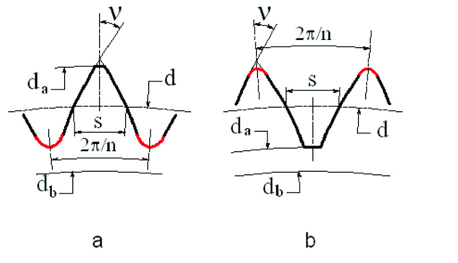
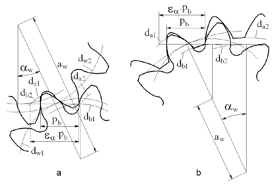
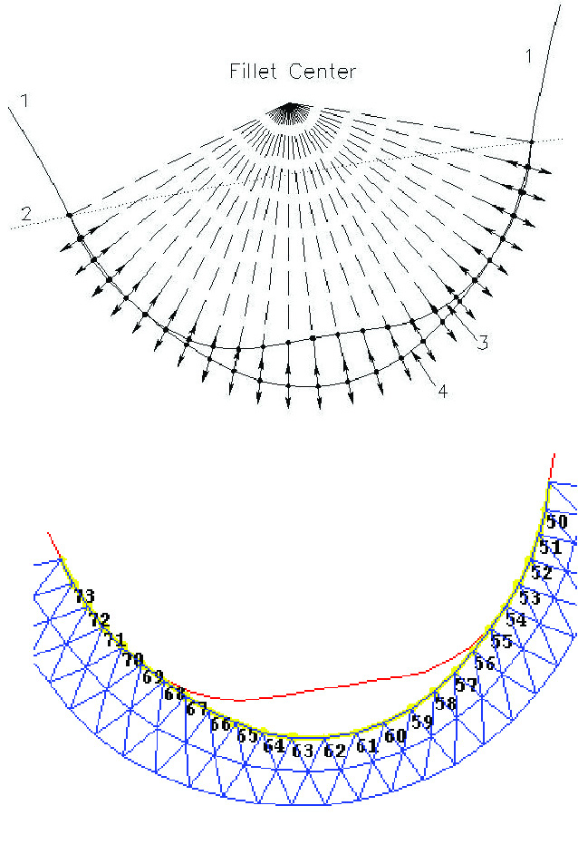
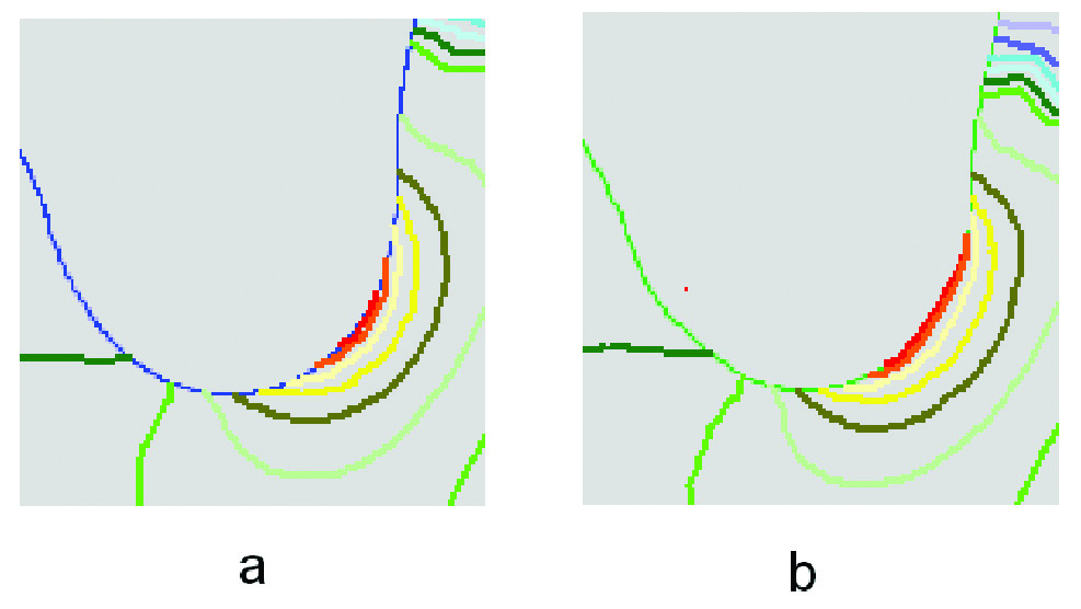
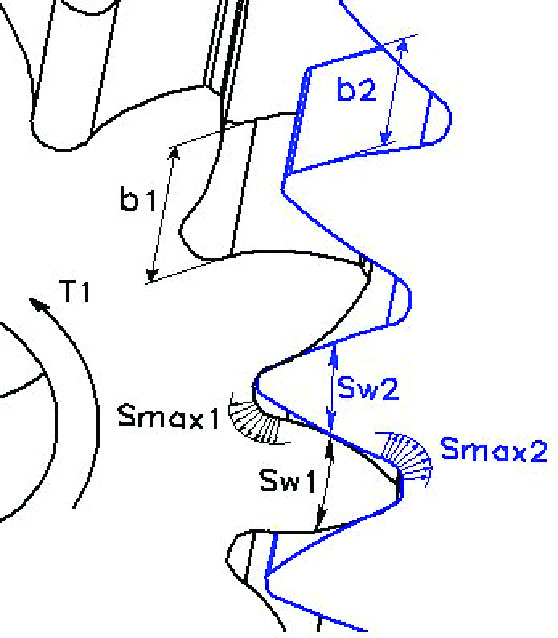
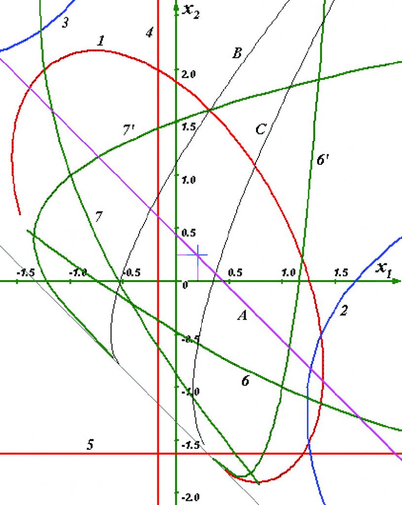
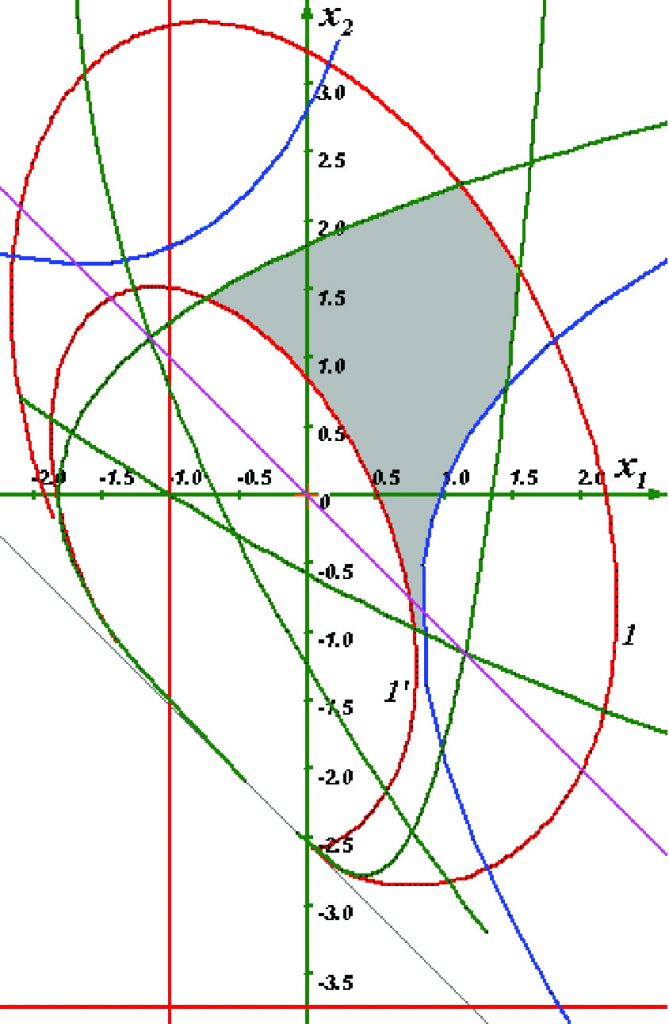
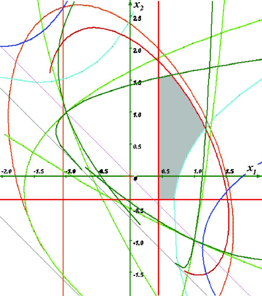
: Passing null to parameter #1 ($string) of type string is deprecated in <b>/home/gearredirontest/public_html/wp-content/themes/Newspaper/loop.php</b> on line <b>52</b><br />")
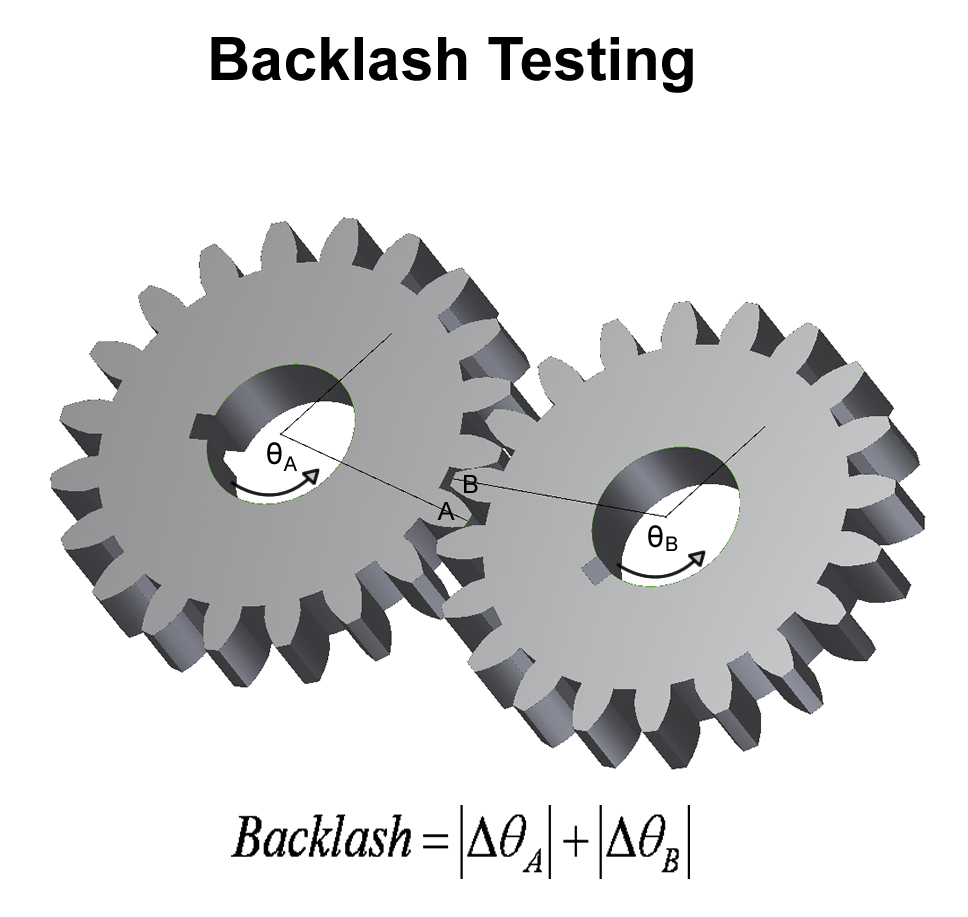
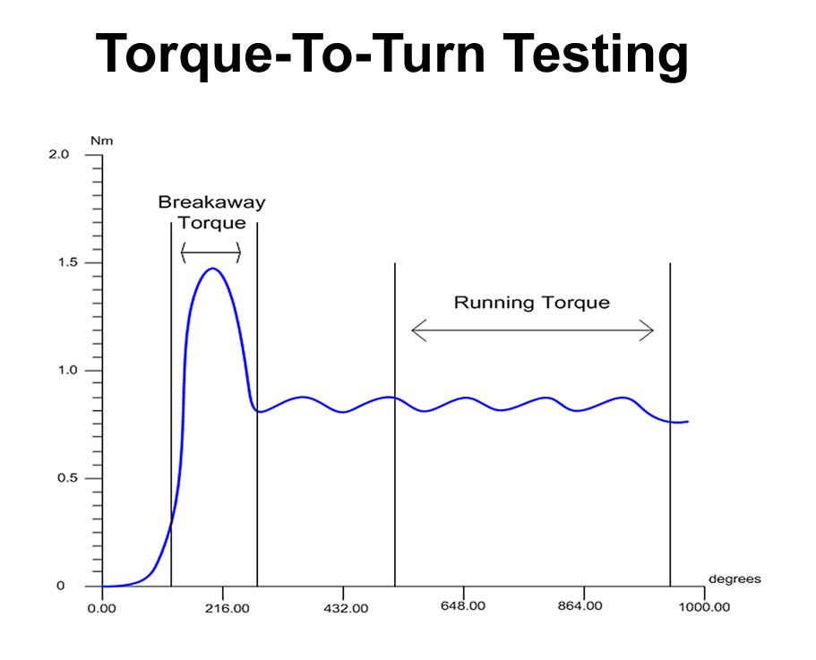
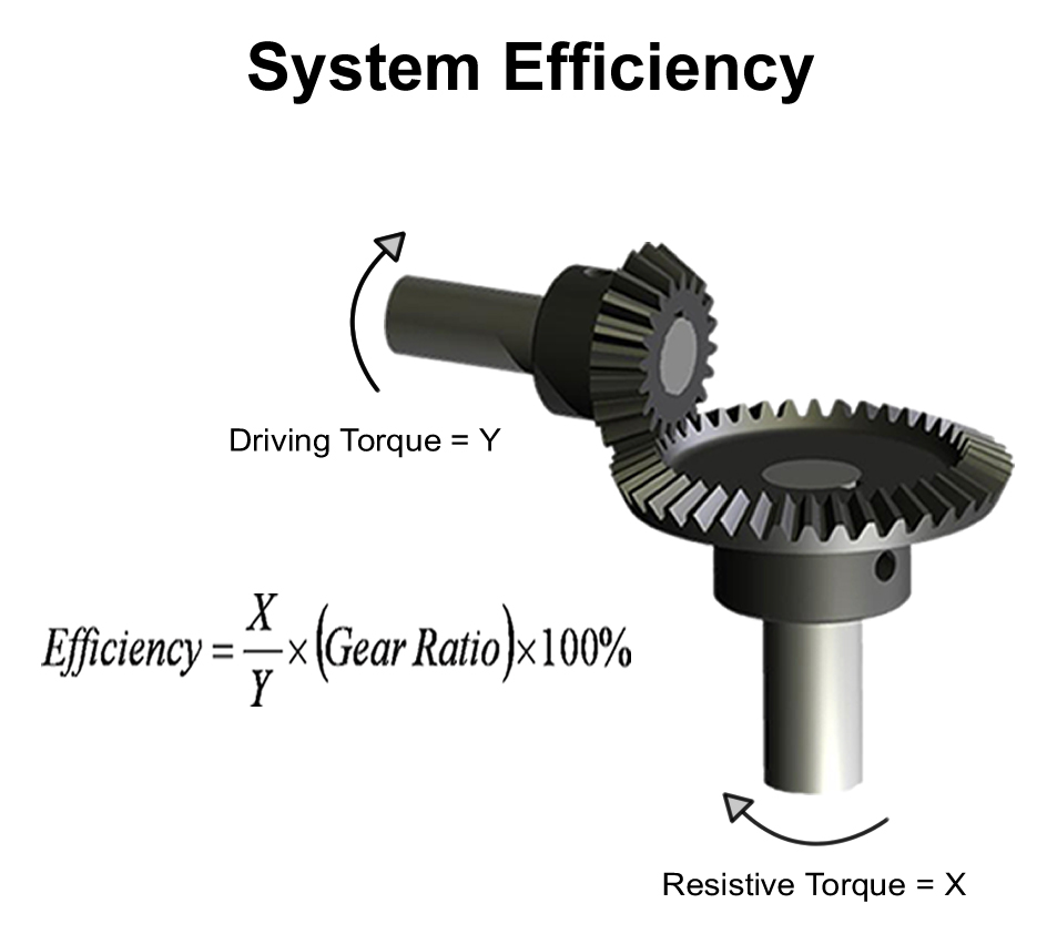
: Passing null to parameter #1 ($string) of type string is deprecated in <b>/home/gearredirontest/public_html/wp-content/themes/Newspaper/loop.php</b> on line <b>52</b><br />")
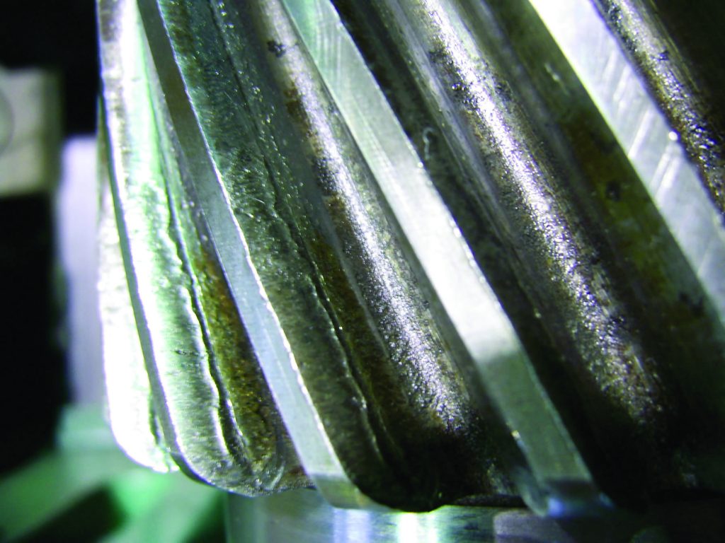
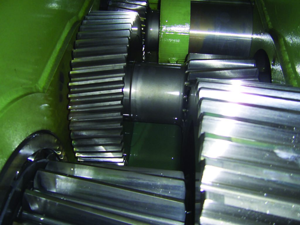
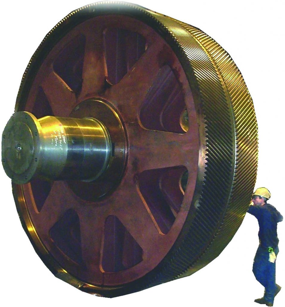
: Passing null to parameter #1 ($string) of type string is deprecated in <b>/home/gearredirontest/public_html/wp-content/themes/Newspaper/loop.php</b> on line <b>52</b><br />")


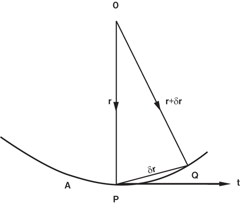
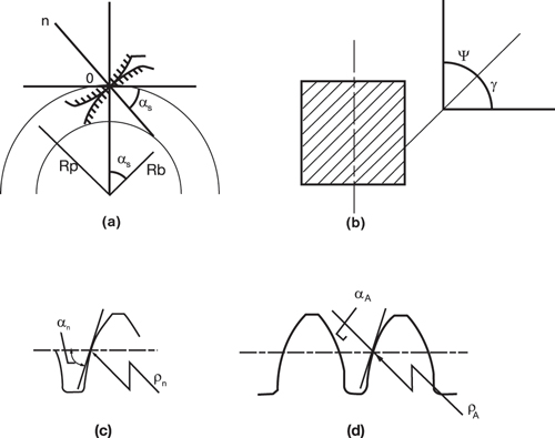
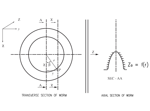