Sam Haines, president of the Gear Motions Companies—Oliver Gear in Buffalo and Nixon Gear in Syracuse, New York—announces the appointment of Barbara Stone to the position of executive vice president of Gear Motions, Inc.
Haines says Stone’s extensive manufacturing and financial expertise makes her a perfect candidate for the growing employee-owned company. “Ms. Stone’s wide-ranging experience includes serving as director of operations and finance at Higbee, Inc., and manager of production control at New Venture Gear (NVG) in Syracuse. She was promoted to the corporate offices of NVG in Troy, Michigan, where she became manager of production control and planning. While at corporate, she was a member of the executive team and was selected to join the Volkswagen Focused Factory Launch Team in Roitzch, Germany. She eventually returned to NVG, where she spent four years as manufacturing area manager.
“Gear Motions is excited to have Ms. Stone become a member of our team. Her remarkable manufacturing and planning experience combined with an extensive financial background will add an entirely new global perspective to our growing company,” Haines says, adding that Stone joined the Gear Motions family in April.
Stone has a bachelor’s degree in accounting from LeMoyne College and an M.B.A. in operations and finance from Syracuse University, were she also taught managerial accounting. She is heavily involved in Syracuse community organizations and currently sits on the boards of the Syracuse Opera Company and the Women’s Fund. Stone is a member of the LeMoyne College Career Center Network Committee, has participated in Leadership Greater Syracuse, and has been a board member of the YWCA and the Consortium for Children’s Services.
Gear Motions, Inc., manufactures all types of cut and precision ground gears. Products include precision spur, helical, bevel, and worm gears, as well as multiple types of belt sprockets, timing pulleys, and splines.
In the 11th century, every combatant carried a sword. Swords were thick and heavy to prevent breakage, making them unwieldy in battle. Those who were wealthy could buy a lightweight, virtually indestructible sword blade from Toledo, Spain. Over the ages the secret of their manufacture was not revealed until the 1970s, when X-ray diffraction detected an induced compressive stress layer on the surface. Further examination revealed subsurface patterns made by repeated blows with a ball-peen hammer. In the 1940s it was discovered how to cast large quantities of uniform steel shot—0.062 in. or less in diameter—that could be used as an abrasive to descale steel. Engineers at General Motors discovered that the process involved cold working and “peening” the surface, thereby providing a permanent compressive stressing of the part.
Shot peening is a cold-working process. The surface under treatment is bombarded with small spherical pieces called shot. As each shot hits it is, in effect, a minute ball-peen hammer dimpling the surface. When the dimples are created the surface fibers yield in tension, the principle being that under the dimple is a hemisphere of highly stressed cold-worked material in compression. Cracks cannot initiate or propagate in compressively stressed zones. The layer created improves the load carrying capacity by increasing the tooth bending fatigue strength. Other benefits include reducing surface fatigue and, in slowing the subsurface crack propagation, pitting is also reduced. The total amount of stress may be increased exponentially. However, the internal stresses cannot break through the compressive barrier created from the process.
The potential benefits for gears vary with the type of gear and its ultimate use. Current standards state that the process should only apply to carburized and case-hardened gears, although gears that are through hardened, induction hardened, and made from ADI can also benefit from shot peening. Applications have a wide range, from automotive, heavy vehicles, and marine to mining and power tools.
ISO gives values based on material quality of 0 percent for ML, 10 percent for MQ, and 5 percent for ME. A proposal from the U.K. to ISO suggested as a general guide high quality gears gained the least, perhaps 15 percent in fatigue strength; gears of lower quality based on machining/heat treatment/material gain most—perhaps 25 percent. Lloyds of London’s Register of Shipping allows an increase in tooth loading for both wear and strength of up to 20 percent with controlled shot-peened gears. Det Norske Veritas marine standard for quality gears (no grinding notches, significant surface decarburization) states that “we add 20 percent to the fatigue limits.” NASA has also conducted extensive test programs to verify the benefits for shot peening gears.
As a general rule, the hardness of the shot should be at least as hard as the gear tooth material. The authority Roy Kern, writing in Heat Treating on solutions to gear failures by use of shot peening provides an example on pinions of 61 to 60 R.C and shot “about 45 to 50 R.C… this was not supposed to work but it did. I have seen at least one other carburized part failing by fatigue, and peening by soft shot solved the problem.” Kern also added “the long-life fatigue strength was improved several fold.”
Calibration of the peening intensity of the shot stream is a function of the shot size, material, hardness, velocity, and impingement angle. J.O. Almen, of General Motors, developed the approved method using one of three standard Almen strips. These SAE1070 spring steel strips are bombarded for a set time period, which results in curvature of the strip. The arc height is measured using an Almen gauge. Control of the depth of compressive stress is very important because the engineer must take other factors into consideration, such as wear, surface finish, and design loads, which result in a tensile stress lower than the level of compressive residual stresses.
One of the latest developments is the use of lasers to generate a shock wave that creates compression on the gear surface. The compressive stresses are much deeper than those achieved by shot peening, providing even more protection against fatigue and corrosion cracking. The process is more expensive and takes longer, and it can be used in conjunction with shot peening. The use of shot peening is growing more popular as engineers realize that increased strength can be obtained without increasing the size of the gear.
Schiess Brighton GmbH—the newly formed company that specializes in the design and construction of very large vertical lathes, horizontal boring mills, and gantry mills—has concluded an agreement with CITIC Heavy Machinery Corp. to design and build a gear hobber that will produce gears up to 16 meters (52 ft) in diameter. CITIC is one of the world’s largest manufacturers of cement making machinery and plant. Under this agreement Schiess Brighton will design the machine and deliver certain critical components. They will also support the construction of this huge machine by CITIC.
The agreement represents an important addition to the line of heavy machine tools offered by Schiess Brighton in that they can now also offer gear cutting machines from 8 m (26 ft.) to 16 m (52 ft.) for the world’s heavy machinery industry. The designs are based on gear hobbers produced by the former German Schiess A.G., which delivered more than 600 of these machines.
When you’re a foundry located in Beaumont, Texas, it’s to be expected that you’ll pursue contracts with the petrochemical industry. But when you’ve been around for 82 years and have seen other businesses suffer for concentrating on a single industry, you learn the importance of diversification.
“And that’s exactly what we’ve done,” says Jeff Freeman, who is vice president of sales for Mabry Castings. “While we do a lot of work with oil and gas companies, we’re also involved in the agricultural, automotive aftermarket, marine, valve and pump, machine tool, and construction/mining markets. And one of our major thrusts right now is to expand on the work we do in the gear manufacturing industry.”
Founded by Claude Mabry in 1925 — and now with 120,000 square feet of space and 47 employees — the company is located on 28 acres, so it’s well positioned to expand in order to meet its customer’s demands. And that’s definitely a possibility, in light of the growth it has experienced in recent years. Freeman credits this, in part, to its embrace of lean manufacturing, as well as the fact that it is able to make most deliveries within four weeks or less. Mabry’s ISO 9001:2000 certification is also a plus, “because that allows us to have conversations with potential customers that we wouldn’t be having otherwise,” he says. “And we’re very competitive in terms of our pricing, as well. I always tell people that while we may not be the least expensive guy on the street, we’re not the most expensive either. And when you factor in our longevity, the quality of our work, and our quick delivery time, that makes our whole package very attractive.”
The quality Freeman mentions is achieved in a number of ways, one being that the company has its own certified metallurgist on staff. “Our metallurgist is also our technical director, and he’s in charge of our sand laboratory where we conduct testing as part of our value-added approach to doing business,” he says. “We also have a spectrograph on site, so that we can analyze everything from the raw materials to the finished part, and we test every ladle of iron we produce and keep the records on file for a minimum of seven years.”
Quality is also assured by the oversight of Eddie Hall, the company’s operations manager. Having joined Mabry Castings in 1982, he has held a number of positions that have provided him with a singular insight into the company’s activities. “I went to work here in the core room before moving into shipping and receiving,” he says. “Then I worked in purchasing, and then quality control, so I’m pretty well-rounded in terms of my background with the company.”
During those 25 years he’s seen a number of major changes, the first involving the company’s purchase by one organization in 1994, and then by the Advanced Metals Group in 1999. More importantly, however, was its shift toward producing more technical types of castings in the early eighties. “Within three or four years of my joining the company we’d gained a foothold in the pump and valve industry, and we also landed the contract to produce all the castings required for the renovation of the cable-car system in San Francisco,” he says. “So that raised our profile and changed the nature of the kind of work we were doing. And that’s really when our efforts at diversification took hold.”
Although it specializes in gray and ductile iron castings, Freeman says that as a member of the Advanced Metals Group — with sister companies including U.S. Castings, Peerless Foundry, Oberdorfer, Ross Aluminum Castings, Robinson Foundry, and the Belcher Corp. — Mabry Castings is in a position to offer gateway services to its customers. “That relationship allows us to talk about a wide variety of materials, including aluminum, so that we can meet their needs whatever their requirements are,” he says. “It makes us that much stronger, in terms of the capabilities we can offer.”
Those offers are made in a very personalized way, since the company doesn’t work through sales representatives. “I attend about 18 trade shows each year, and we exhibit in five or six of them, so I spend a lot of time meeting new people and learning about their company’s needs,” Freeman says. “And I always tell them that when I say something will happen, it will happen, because I’m directly responsible for making sure it does. If they need me to visit their facility, I’ll be glad to do so, because it’s important for them to know we’re taking a personal interest in their business.”
As for what Mabry Castings has to offer gear manufacturers, Freeman says it’s quite simple. “We’ve spent 82 years building our reputation, and we maintain that by always living up to our customer’s expectations.” MORE INFO Call (409) 842-2223, send e-mail to sales@mabrycastings.com, or visit online at www.mabrycastings.com.
Haas Automation Asia is pleased to announce the official opening of its brand-new 72,300-square-foot China Headquarters and showroom in Shanghai. The move comes just three years after the company first opened its Asian operations in the city’s Waigaoqiao Free Trade Zone. In that time Haas’ business in China has increased dramatically, and the company has outgrown its original location.
As well as providing vital additional office space, the new building incorporates a 6,700 square-foot showroom, allowing some 20 Haas machines from the company’s extensive and growing range of affordable CNC machine tools to be exhibited and demonstrated simultaneously. Also part of the facility is a 32,300 square-foot warehouse for maintaining a stock of 200 new machines, allowing delivery to almost anywhere in China within five days of receiving an order. According to Haas Asia Managing Director Fischer Mou, the relocation marks an important milestone for the company. “Since establishing Haas Asia we’ve exceeded our annual sales targets in all of the key China markets. In the past year alone we’ve experienced a sales increase of more than 30 percent. This is in line with the growth Haas has enjoyed in other markets around the world and reflects the universal appeal of low-cost, high-quality CNC machines.”
The new headquarters includes a 6,000 square-foot spare parts warehouse run by factory-certified support personnel, which will provide same-day dispatch for more than 90 percent of requisitions, with 100 percent of requisitions dispatched within 24 hours. The new facility also includes a modern, fully equipped training area, with three classrooms and a 1,550 square-foot Technical Education Center, where Haas personnel will instruct Haas Factory Outlet (HFO) service engineers and customers from all over China.
Five Haas Factory Outlets currently are in operation in China, with locations in Shanghai, Guangzhou, Shenyang, Qingdao, and Chongqing. An additional seven HFOs are scheduled to open throughout the country by year’s end, further expanding Haas Automation’s already substantial customer-support network in China. “As both our Chinese customer base and our distributor network increase, we intend to offer the best service and support in the industry,” Mou adds. “Our investment in the new office, showroom, and parts warehouse will help ensure that we do just that.”
Material selection is one of the most crucial decisions made in the design, manufacture, and application of large structural components. Material selection naturally influences the entire performance of the design, and thus it is critical that informed decisions are made during the design stage. Steel castings and steel forgings are two alternatives for large structural components. For many design engineers it is often assumed that a forging is a better product because it is formed or worked during the manufacturing process. It also assumed that castings are inferior because they may contain porosity. Nothing could be further from the truth. Each process has its advantages and disadvantages. It is just as possible to produce an inferior product whether it is a forging or a casting. This paper will present an honest evaluation of castings and forgings, so that those in the design community can make an informed choice.
Introduction
This paper will concern itself with the differences between forged and cast steels in heavy sections. Heavy sections will be interpreted to mean parts in excess of 10 tons and a minimum metal section of 200 mm (5”). All steel products, whether they are cast or wrought (forged), start from a batch of molten steel that is allowed to solidify in a mold. The difference is that a wrought product is mechanically worked by processes such as rolling or forging after solidification, while a casting is not.
Melt Shop Practice
The process of steel making is essentially the same for both wrought and cast steels. Liquid steel is principally an alloy of iron and carbon. Other metals such as chromium, nickel, manganese, and molybdenum are added as alloying agents to impart particular properties to the steel. The raw materials used to make steel also contain undesirable elements such as phosphorus and sulfur, which form inclusions in the steel that can never be completely removed from the steel. Thus the quality of both forgings and castings is dependent upon the quality of the molten steel that is poured into the mold.
Since most forge shops purchase their steel ingots, they are dependent upon the steel mill to control the quality of the raw material that is used in their product. This also limits forge shops to supplying the standard alloy grades that the steel mill offers. Conversely, steel foundries have to both make and pour their own steel to produce a casting, and thus have full control of the metal that is used to produce the casting. This also allows the foundry to supply virtually any alloy grade that the customer may want.
Liquid steel has a high affinity for oxygen, and it will form oxide inclusions that can also become trapped in the final product. Molten steel must be handled properly to minimize the formation of re-oxidation products. Once the steel is refined in the melting furnace it is tapped into a ladle, which is a refractory lined vessel made to handle molten steel. Good steel making practice dictates the use of a bottom pouring ladle. The reason for this is that a slag layer is developed on top of the molten steel by use of fluxes. This slag layer is less dense than steel, and thus floats on top while at the same time forming a protective barrier from the atmosphere. This protective barrier is maintained since the steel is poured from the bottom of the ladle. The bottom pouring technique is used for both steel castings and for steel ingots. (Figure 1).
Figure 1: Bottom Pouring in a Steel Foundry
One important distinction between wrought and cast steels is the de-oxidation practice that is used. Wrought steels are typically “aluminum killed,” which means that a small amount of aluminum is added during the melting process for the purpose of removing oxygen from the steel. While very effective at removing oxygen, the aluminum forms microscopic aluminum oxide particles, which are abrasive during the machining process. Some steel casting shops de-oxidize with calcium, which also removes the oxygen but produces a softer, more machinable inclusion.
Forging Process
Wrought or forged materials by definition are made from cast ingots, which are then mechanically worked after solidification. Ingot castings are the raw materials from which all wrought products such as forgings, plate, and barstock are produced, and they are nothing more than a casting that is produced by pouring the liquid steel into a reusable metal mold. The cast ingot structure consists of different zones that contain porosity and segregation.
After solidification the ingot is hot forged into the desired shape using a hammer, press, or ring-rolling machine. As the forging is hot worked into shape, the inclusions, porosity, and grains within the steel ingot are forced to flow in the direction the part is being worked. This imparts directionality to the finished part. According to the forging industry, this grain flow makes forgings superior to castings. However, the fact is that although the mechanical properties of a forging are higher in the longitudinal direction (direction of working), they are significantly lower in the transverse direction, or perpendicular to the grain flow. Thus, when using a forging the design engineer needs to evaluate the loading characteristics in both the transverse and longitudinal direction. The effects of grain flow are shown in Figure 2.
Figure 2: Forging Grain Flow, Crane Hook
Large forgings are hammered or pressed into rough shapes, which then require extensive machining or welding to other components to produce a more complex shape. This adds to the cost of the overall product. Large forgings are limited as to the amount of mechanical working that can be done.
The forging industry typically refers to the term “reduction ratio,” which is the ratio of cross-sectional area before and after forging and is used as a means to specify the quality of the forging. The typical standard for very large forgings is to require a minimum of three reductions. It is recognized by the forging industry that excess hot working can impart too much directionality into the part.
Forgings are subject to process variables and have the same potential for defects as any manufacturing process. For example, a large forging may actually burst or crack internally during forging if not heated properly (Figure 3).
Figure 3: Internal burst in a large forging
Casting Process
Most steel castings are produced in expendable sand molds. The mold is produced by forming sand around a pattern, which is a replica of the finished part. Molding sands are mixed with materials that will allow it to hold the desired shape after the pattern is removed. Holes or cavities are created by assembling sand cores in the mold. The pattern equipment also includes the gates and risers which are needed to produce a quality casting. The gating system is designed to allow the metal to flow into the mold in a controlled manner. Risers are reservoirs of molten metal which allow the casting to solidify without shrinkage porosity.
Post solidification processing includes sand removal or shakeout, removal of gates and risers, inspection, weld upgrading, and heat treatment. The main advantage of the casting process is its versatility. Castings are best suited for complex geometries that cannot be easily produced by the forging process.
The principal difference between a casting and a forging is that the final part shape is created when the molten metal solidifies in the mold. Since the sand mold produces the desired finished shape, all that remains is to process the casting through various finishing operations in the foundry. This processing does not alter the directionality of the casting. A steel casting is homogenous. This means that the mechanical properties of a casting are the same regardless of the direction of applied stresses.
It is very important to understand the underlying principles that dictate how a casting solidifies. As steel cools in the mold it naturally changes from a liquid to a solid, resulting in volumetric contraction. Additional feed metal in the form of risers must be supplied to the casting to make up for this loss in volume. There also needs to be a pathway for the additional metal to feed the casting as it solidifies. If a region of a casting is isolated from the riser, a shrinkage cavity will form (Figure 4). In this case it is necessary to add material to allow the molten metal to be properly fed from the molten riser.
Figure 4: Directional solidification and design
The foundry engineer evaluates the shape of the casting and then determines how to modify the casting so that solidification progresses from the thinnest section back through progressively heavier sections. This progressive, controlled manner of solidification is termed “directional solidification.” Directional solidification can only occur if the temperature gradient is controlled by proper casting design. The temperature gradient can be modeled using solidification software. Thus the foundry engineer can validate the casting design by solidification modeling before the part is actually poured.
All castings naturally begin to solidify at the mold wall, because that is where the heat is first extracted from the molten metal. Solidification continues to proceed in the regions of the casting that are cooling the fastest. Good casting design practice seeks to make sure that the last part of the casting to solidify always has a supply of molten metal available to avoid the formation of shrinkage cavities. Since the last area to solidify is primarily influenced by part shape, it is critical that the casting user and the foundry work closely together to make sure that the part is designed in such a way as to optimize its castability, while at the same time taking advantage of the castings processes’ ability to produce the part to a near net shape.
Mechanical Property Comparisons
As previously stated, the forging process produces a part that is anisotropic. This means that the mechanical properties of a forging are better in the longitudinal direction (parallel to lines of flow) versus the transverse direction (perpendicular to lies of flow). Conversely, a casting is homogeneous; this means that the mechanical properties of a casting are the same, regardless of the orientation of test bar material (Figure 5).
Figure 5: Test bar orientation
In order to demonstrate this difference a 5” thick test casting was poured from a typical low alloy cast steel. Equivalent test material was also cut from a 5” thick plate of rolled 4340 steel. Both test plates were then heat treated in the same production furnace load. Thus the test materials were equivalent in all respects of processing, except that one was cast and the other was wrought. Test bars were removed from the test plates in the orientation shown in Figure 5.
Test results shown in Table 1 (Figure 6) demonstrate that the mechanical properties of the cast plate are essentially the same regardless of test bar orientation. The mechanical properties of the wrought plate are lower in both the transverse and through thickness orientations, especially the ductility (indicated by the percentage of elongation and percentage of reduction in area), which shows a significant degradation when compared to the longitudinal direction. The tensile ductility of the cast material is significantly higher than for the wrought material in the through thickness orientation, although lower than in the longitudinal direction.
Figure 6: Mechanical test comparison, wrought and cast plates
The same directionality effects are demonstrated when comparing the fatigue strength of cast and wrought alloys. Figure 7 shows that the un-notched fatigue properties of the cast steel test are below that of wrought steel in the longitudinal direction, but above wrought steel in the transverse direction. However, the notched fatigue properties of test bars of cast steel are actually superior to wrought steel, regardless of orientation. This demonstrates that cast steel is less notch sensitive than wrought steel. Notched fatigue properties are a more accurate representation of actual service conditions because most large parts — whether cast or forged — would be expected to have some type of a notch.
Figure 7: Fatigue properties
Non-Destructive Testing
Large, heavily loaded parts are often non-destructively tested (NDT) in order to verify internal part integrity. The most common methods are ultrasonic (UT) and radiographic testing (RT).
Common specification pitfalls are to discount the effects of surface finish and machining when specifying NDT methods. For example, since UT functions by measuring reflected sounds waves, it works best on a part that is machined and has two parallel surfaces. Using UT on an un-machined surface compromises the sensitivity of the test. RT indications will change appearance before and after machining since the section thickness is reduced.
The main benefit of RT is that a permanent record is created. The acceptance criteria are based upon a comparison against ASTM reference radiographs, which are rated 1 through 5 (best to worst). The SFSA (Steel Founder’s Society of America) sponsored a research project to determine the applicability of the ASTM referenced radiographs. In essence, the study had experienced ASNT Level III radiographers evaluate the reference radiographs in a blind test. This group was able to agree on the best and worst conditions (levels 1 and 5). However, this expert group could not agree on which reference radiographs represented the middle levels of 2, 3, and 4.
Both of these examples demonstrate that each method has its limitations, and the purchaser and the producer need to understand these limitations. Application of a stringent NDT requirement does not necessarily result in a high-quality part.
Summary
The main difference between a steel casting and a forging is that the forging is mechanically worked after solidification. This mechanical working imparts directionality, or anisotropy, to the forging. Castings and forgings are both susceptible to manufacturing problems and misapplication by the buyer. In general, a forging is best suited to simple configurations that can be easily worked in a die or other tooling. It is also suited to applications in which the principal applied stresses are the same as the direction of mechanical working. A casting is best suited to complex shapes, custom or tailored chemistries, and to applications that are subject to multi-axial stresses.
Casting buyers need to work closely with foundries at the design stage in order to insure that the design is able to take advantage of directional solidification. The poor quality image of castings is often the result of the buyer not understanding this process. The casting buyer must also understand that there are limitations to relying solely on NDT to verify quality. Quality is best enhanced by using tools such as solidification modeling at the design stage to insure the production of a high-quality product.
The Association For Manufacturing Technology (AMT) announces its partnership with Ethnometrics to measure the “purchase experience” at IMTS 2008 in September 2008. IMTS is the largest show to apply this type of research to the trade show experience.
“Purchase experience” refers to the science of measuring the effectiveness of a selling environment in creating a fulfilling and memorable interaction between buyer and seller. Ethnometrics combines qualitative and quantitative research with behavioral measurement techniques to provide insights that lead to significant improvement in the value of the show for attendees and better ROI for exhibitors.
“Ethnometrics will provide us a data-driven method of measuring the IMTS experience,” said Peter R. Eelman, AMT vice president-exhibitions. “Given the large number of exhibitors, the floor space IMTS covers, and the debut of McCormick Place West, this new level of information will provide facts to support strategic decisions that can drive growth. It is a great value-added tool that will help us strengthen our partnership with exhibitors and provide a dynamic assessment of the value attendees and exhibitors gain from IMTS, and how that value can be improved.”
The IMTS analysis will measure such attributes as the effectiveness of show layout and design for optimum traffic flow, key characteristics and behaviors that attract attendees and encourage them to engage and interact, and the effectiveness of exhibitors in creating an environment that promotes interaction from initial contact to final purchase. In addition to the overall study, plans are being made to offer the Ethnometrics research tool to IMTS 2008 exhibitors so they may gain insights into attendee behavior centering on their specific exhibits.
The International Manufacturing Technology Show (IMTS) is the largest and longest running manufacturing technology trade show in the United States is held every other year at McCormick Place in Chicago. IMTS is ranked among the largest trade shows in the world. Recognized as one of the world’s preeminent stages for introducing and selling manufacturing equipment and technology, IMTS attracts over 90,000 visitors from every level of industry and over 40 countries. IMTS is owned and managed by AMT.
Founded in 1902, AMT represents and promotes the interests of American providers of manufacturing machinery and equipment. Its goal is to promote technological advancements and improvements in the design, manufacture, and sale of members’ products in those markets and acts as an industry advocate on trade matters to governments and trade organizations throughout the world.
Ethnometrics is the industry leader in bringing retail store behavioral research to the exhibit floor. They are a six sigma-based consulting firm committed to providing measurement driven customer solutions to business applications for Fortune 500 companies like Best Buy and Whirlpool. Their expertise focuses on the fact that business entities spend countless resources on items that they think create value for customers but never verify the effectiveness of these resources in delivering that value. Ethnometrics’s ultimate goal is to optimize this spending by eliminating and/or redirecting it to venues that provide the maximum return on investment in order to make IMTS a world class experience for those involved in exhibiting, attending and managing the shows.
The form grinding process has dramatically increased the efficiency of gear grinding machines, and consequently the productivity of gear shops. New tools and advanced CNC controls facilitate faster cycle times; this pushes the process closer to its limits, however. Progress is made in small steps, but only with less stable process conditions as a result. Faster stroke speed and larger infeed increase the risk of burning. Additionally, it is important to increase the lifetime of the gearbox in order to reduce size and noise, and higher quality is needed to achieve this. These requirements, though, are contradictory to one another. And so in order to reduce costs while increasing quality without adding risk, it is necessary to consider the complete chain of production.
Niles ZP X B Series
Heat treatment divides the production of gears in soft machining and hard finishing and generates a natural break between them. Niles has developed a machine series that is capable of running the full cycle of hard finishing, after heat treatment. The new machine combines the Niles ZP gear grinding machine with a second column for inside-diameter (ID) and face grinding, to finish the gear in one setup. The main gear grinding column is equipped with hydrostatic guideways, integrated into the machine design for stability and accuracy. The second column for ID grinding is positioned 90° to the primary gear grinding column.
The rotary table for the ZP series is supported by double-acting hydrostatic bearings and driven by an electrical-direct drive — the newest evolution in the development of gear grinding machines. Completely contact-free, this combination renders machine’s rotary table effectively wear-free for life. This drive allows the rotational speed to permit grinding of both the gear teeth and the inside diameter. The electrical-direct drive provides the highest positioning accuracy for gear grinding, and high-speed rotation for inside-diameter grinding.
Niles ZP 30 B Design
The first combination machine, the Niles ZP 30 B, was installed in 2005. The machine is designed to grind gears of up to three meters in diameter (Figure 1), and its column is equipped with a stroke slide and is capable of using different grinding heads, depending on the application. The column can be equipped with an internal gear-grinding head or steady rest as well as an ID grinding spindle. The dresser is located at the machine base. The dressing disc is designed as a cup to dress the face and the outside diameter (OD) of the grinding wheel. This design makes it possible to grind both the ID and faces. (See Figure 2 for ZP 30 B machine data.)
Figure 1: ZP 30 B machineFigure 2: ZP 30 B machine data
Niles ZP 10 B Design
The next step in our development was to design a machine for gears up to one meter in diameter (Figure 3). All main assembly groups — such as the main column for gear grinding, the second column for ID grinding, and the rotary table — are built on one rigid machine bed. The second column carries the stroke slide with the grinding slide and the rotary dressing spindle for ID and face grinding. The ID grinding spindle is mounted to the grinding slide and direct-driven by a servo motor. The liquid cooled spindle can be easily changed to use whatever spindle is suitable for the application. The first installation of these machines will be in 2007. (See Figure 4 for ZP 10 B machine data.)
Figure 3: ZP10 B machineFig. 4: ZP 10 B machine data
The Design Process
1: Reduce Production Steps
Our first goal in the design of a combination machine was to reduce time-consuming production steps — and, consequently, the cost per piece — without increasing risks. Conventional methods require two different machining processes and several setups on both machines. The first process includes finishing the ID with an ID grinding machine or hard turning machine, depending on the quality requirements, and to grind or turn the face and datum to align at the second machine. The second machining process is gear grinding with a gear grinding machine.
Using two machines obviously duplicates many steps — machine setup, clamping and unclamping, alignments — and there’s also the time it takes to transfer the gear from one machine to the other. A combination machine reduces these machining process steps by 50 percent.
2: Increase Quality
Increasing quality was our next task in the machine design. To accomplish this, the ID and the gear teeth were ground in one setup without unclamping. This eliminates the errors formerly caused by two different clamping tasks. The reference of the gear teeth to the bore is no longer dependent on the alignment and geometry of two different machines. The combination machine creates a very high reference quality between ID and gear teeth by using the same setup and the same table.
This new processing methodology set the stage for another quality upgrade. After placing the gear at the machine table, it is aligned only once. The alignment is done on the machine by measuring the best center position to minimize tooth grinding stock. The machine calculates a new workpiece axis based on the measuring results. The bore and the teeth are ground according to this axis. The case depth will be approximately equal over all teeth of the gear due to this method, and the resulting equalized surface hardness can potentially reduce the depth of hardening to further optimize the overall process.
3: Reduce the Stock
The gear grinding process is the last and most expensive process in gear production. The number of scrapped or reworked parts at this stage of grinding should be as minimal as possible, with zero as the target. At this point in design we focused on decreasing the number of scrapped and reworked parts.
Experience shows us that after you align the gear according to the bore, as in conventional methods, the gear teeth cannot be cleaned up. The gear has to be reworked or it must be scrapped. One solution to this could be to increase the stock before grinding, but more stock means more time is needed for heat treatment—and gear grinding, too. If, however, we align the part to the gear teeth instead of the bore, there is equalized stock at the gear teeth, therefore reducing the number of teeth that are missed in cleaning. Meanwhile, the grinding stock for the bore grinding is only slightly altered, the time for heat treatment and gear grinding decreased, and the number of reworked or scrapped parts significantly diminished.
Saving Costs
Since ID grinding is faster than tooth grinding, an ID grinder can provide parts for multiple gear grinding machines. When a machine breaks down, the ID grinder halts the production of expensive gear grinders. A combination machine eliminates this problem by doing the job of two hard finishing processes. One machine means there is only one control for one operator to manage, and simplified machine maintenance translates into significant savings in service costs. Machine idle time, transferring parts from one machine to the other, and waiting for the next machine are steps that are now eliminated, and workflow is expanded.
Applications
The Niles ZP 30B is used for small-lot size production, as in marine applications. The first of a large variety of applications for the new ZP10 B is to increase the series production of planets for wind energy gearboxes. The combination machine will save setup, grinding, and idle times. The part flow will be increased in order to decrease the cost per piece. The Niles ZP 10 B paves new paths in the production of planetary gears.
The Niles combination machines offer another successful step toward streamlining our processes, increasing our efficiency, and generating a more productive means of manufacturing high-quality parts.
Niles also offers other innovative and demonstrated technologies. The ZP25i machine fills the demand for a highly productive internal gear grinding machine. The ZP25i features a heavy and stiff internal head with an independent dresser. It provides productive tooth grinding of larger internal ring gears. Machines such as the ZP 08 for pinions (Figure 5) and the ZP 12(15) for bull gears are additional Niles technologies.
Figure 5: ZP 08 machine
Niles is a part of the KAPP Group; a leading supplier of innovative technology for hard-finishing gears dedicated to the automotive, aerospace, windmill, construction, and mining industries.
Officials of Philadelphia Gear Corporation have announced the availability of two versions of the company’s proprietary CORE, or Continuous Oil Rescue Equipment. Launched as an alternative to traditional barrier filtration techniques, the CORE models filter metallic particles as small as one micron (one-millionth of a meter). Unique to Philadelphia Gear, these filters are now designed to fit lubrication systems ranging from .5 up to 2.0 inches in diameter, providing protection for critical rotating equipment not previously available.
According to Philadelphia Gear CEO Carl Rapp, the durability of each CORE filter is matched only by its compactness. “With a magnetic half-life of 50 years, each CORE unit is effectively projected to outlive virtually any machine you put it on.”
The larger unit, designed for lubrication systems between 1.25 and 2.0 inches in diameter, weighs approximately 20 pounds and holds more than two pounds of debris. The smaller unit, designed for lubrication systems between .5’ and 1.25 inches, weighs approximately five pounds and holds nearly one pound of debris before cleaning is necessary. Both CORE versions hold significantly more contaminant than a conventional filter because of their three-dimensional storage capacity. This increased capacity also allows for longer periods of operation without service.
Inside the cast aluminum housing is an assembly of five magnets, each surrounded by a set of steel flux plates. A series of “collection zones” are machined into the plates such that oil flow is never restricted, even as debris begins to build up inside the filter.
“These plates create magnetic fields that strip ferrous metal contaminants out of the lubricant, while keeping the pressure flow at its maximum, constant rate and preventing debris from washing off back into the lubricant,” Rapp explains. “This is a significant advantage over other methods of filtration.”
Additionally, the units are sized—even in very contaminated situations—to not require excessive maintenance. A routine cleaning is only required once a year and is easily accomplished by blowing air across the inside. The units can be installed in duplex configurations so that they can be changed out or cleaned without ever shutting down the gearbox itself. One particular feature of the CORE is that is has virtually no pressure drop and therefore is particularly suitable for installing upstream of pumps for additional protection. For more information call (800) 766-5120 or visit online at [www.philagear.com].
This paper is aimed at the development of a novel design of precision gear hob for the machining of involute gears on a conventional gear-hobbing machine. The reported research is based on the use of fundamental results obtained in analytical mechanics of gearing. For solving the problem, both the descriptive-geometry-based methods (further DGB-methods) together with pure analytical methods have been employed. The use of DGB-methods is insightful for solving most of the principal problems, which consequently have an analytical solution. These analytical methods provide an example of the application of the DG/K-method of surface generation earlier developed by the author. For interpretation of the results of research, several computer codes in the commercial software MathCAD/Scientific were composed. Ultimately, a method of computation of parameters of design of a hob with straight-line lateral cutting edges for the machining of precision involute gears is developed in the paper. The coincidence of the straight-line lateral cutting edges of the hob with the straight-line characteristics of its generating surface eliminates the major source of deviations of the hobbed involute gears. The relationship between major principal design parameters that affect the gear hob performance are investigated with use of vector algebra, matrix calculus, and elements of differential geometry. Gear hobs of the proposed design yield elimination of the principal and major source of deviation of the desired hob tooth profile from the actual hob tooth profile. The reported results of research are ready to put in practice. This is the conclusion of a two-part series. Part I can be downloaded at www.gearsolutions.com
Introduction
The pitch diameter neither of the new hob, nor of the completely worn hob, could be used for the computation of parameters of design of the gear hob. For accurate computations it is recommended to use pitch diameter of the partly worn gear hob that correlates with outside diameter of the cutting tool. Outside diameter of the new gear hob is equal to do.h (Figure 10), while outside diameter of the completely worn gear hob could be computed from the equation (do.h − Δdoo.h ). For computation of the outside diameter reduction Δ doo.h , the following approximate equation
is derived. Here it is designated that: L is a distance between two neighboring hob teeth that is measured along the helix on the outside cylinder of the hob (Figure 10), αrh is clearance angle at the top cutting edge of the hob tooth, and nh is effective number of the hob teeth.
Figure 10. The involute gear hob after it has been reground.
For involute hobs with straight slots, nh is always an integer number, and it is always equal to the actual hob teeth number n(a)h which is usually in the range of nn(a)h = 8∼16 [because of this, the distance L can be computed from equation ∪L=(π⋅do.h)/nn(a)h ].
For gear hobs with helical slots, the effective hob teeth number nh is always a number with fractions. Moreover, the actual value of nh depends upon the hand of helix of slots. This is due to that in the last case the distance L is computed from the equation ∪L=(π⋅do.h)/nn(a)h ]+Px.h ⋅Nh ⋅ cos λrf ⋅ sin λrf [1], [13], [14] and others. Here is designated: d o.h is outside diameter of the hob, Px.h is axial pitch of the hob, Nh is the hob starts number, λrf is lead angle of the hob rake face λrf is the signed value).
Equation (25) is a simple one. It is an approximation, which returns reasonably accurate results of computation.
The performed analysis of the gear hob design reveals that decrease of number of starts Nh of the hob (Figure 11) (a), increase of normal pressure angle φn (Figure 12) (b), increase of the hob-setting angle ζh (Figure 13) (c), and increase of the hob pitch diameter dh (Figure 11 through Figure 13) (d) result in reduction of the angle ξ of the rake surface orientation.
Figure 11. Impact of number of starts Nh of the involute hob onto the actual orientation of the rake plane determined by the angle ξ ( m = 10 mm, φn = 20 deg , ζh = 3 deg , nh = 10 , αt = 12 deg ).Figure 12. Impact of the involute hob normal pressure angle φn onto the actual orientation of the rake plane determined by the angle ξ ( m = 10 mm , Ng= 1, ζ h = 3 deg , nh = 10 , αt = 12 deg ).Figiure 13. Impact of the hob-setting angle ζ h onto the actual orientation of the rake plane determined by the angle ξ ( m = 10 mm, 20 deg φn = 20 deg, Ng = 1, nh =10, αt = 12 deg ).
The plots (Figure 11 through Figure 13) are created using commercial software MathCAD/Scientific. Unfortunately, the lack of capabilities of MathCAD/Scientific imposed restrictions on graphical interpretation of the functions ξ = ξ (Nh) , ξ =ξ(φn)n, ξ =ξ(ζh), and ξ = ξ (dh). The lack of capabilities is the sole reason that the listed functions are interpreted as a function ξ = ξ (dh) under various values of the gear hob number starts Nh (Figure 11), normal pressure angle φn (Figure 12), and the gear hob-setting angle (Figure 11 through Figure 13). However, Figure 13 provide clear understanding of the impact of the above mentioned parameters of the gear hob design onto the rake face inclination (ξ).
It is important to single out here that the hob pitch diameter could be significantly increased due to the application of hobs with internal location of teeth, the use of which allows hobbing of numerous gears either in one set-up or simultaneously. Internal hobbing could be performed with the application of a gear hobbing machine of special design [13].
One could suppose that in the ideal case, the equality ξ = −ψh has to be observed. Actually, this equality is not of importance for the design of finishing, as well as of semi-finishing precision involute hob. Finishing and semi-finishing gear hobs cut thin chips, the thickness of which is comparable with the hob cutting edge roundness ρh . Therefore, not the rake angle but the cutting edge roundness directly affects the chip removal process in hobbing of precision involute gears.
For precision gear finishing hobs of big modulus m, for example for semi-finishing and finishing skiving hobs, the top cutting edges are out of contact since the gear bottom land is completely machined on a gear roughing operation [8], [18].
Therefore, the geometry of the top cutting edge is out of importance for the finishing and semi-finishing precision gear hobs of the developed design.
The geometry of the active part of the cutting teeth of the involute hob is a subject of another paper to be submitted. Investigation of this problem is of importance, firstly because the rake face is not orthogonal to the generating surface T of an involute hob.
An approximation of the rake surface of the gear hob could be feasible. In the event of approximation of the rake surface, the rake surface could be shaped in the form of a screw surface of that same hand as the hand of the screw involute surface of the generating surface T of the gear hob. Helix angle of the screw rake surface is equal to ψrf = 90°−ξ.
Either the rake surfaces or the clearance surfaces of the worn gear hob could be reground. A novel technology of the hob regrinding operation has been developed. A comprehensive analysis of the gear hob regrinding operation is a topic to be reported in another paper.
4. Hob Design Extension
Here we consider a precision hob for machining of a modified involute gear as an extension of the original design of a gear hob. The reported results of analysis of inclination of the rake surface of the involute hob teeth (see Section 3) uncovered an opportunity of hobbing of modified involute gear (Figure 14).
Figure 14. Modification of the gear hob tooth profile.
The straight-line lateral cutting edges of the gear hob align with the straight-line characteristic Eh of the hob. Searching for an opportunity of reduction of the rake face inclination (i.e. reduction of ξ ), one could turn his/her attention to a possibility of turning of the characteristic Eh (and the gear hob cutting edge as well) through a certain angle Φ about a point K on the pitch line of the auxiliary rack R of the gear hob. The rotation of Eh definitely reduces the rake-face inclination ξ . However, at that same time the rotation of Eh results in curved lateral profile of the auxiliary rack Rm tooth5. The last gives a possibility of hobbing of modified involute gear. For this purposes a gear hob of novel design is developed [17].
The required angle Φ can be computed from the Euler’s formula
Here, the principal radii of curvature R1.T and R2.T of the modified auxiliary rack surface Rm are equal to [1] [19]
Finally, one could come up with an equation
for computation of the necessary value of the angle Φ .
A possibility of modification of the gear tooth profile could easily be illustrated by the characteristic curves of novel kind recently developed by the author [20], say by the AnR(T) -indicatrix of the first kind, and the Ank(T) -indicatrix of the second kind. The AnR(T) -indicatrix of the first kind could be given in matrix representation
This characteristic curve illustrates the distribution of normal radii of curvature RT(Φ) of the surface T in differential vicinity of K (Figure 15).
Figure 15. Distribution of normal curvature in the differential vicinity of a point on the surface T of the FETTE gear hob (DIN 8002A, Cat.-No 2022, Ident. No 1202055).
The Ank(T) -indicatrix of the second kind could also be given in matrix representation
This characteristic curve illustrates the distribution of normal curvature kT(Φ) of the surface T in differential vicinity of K (Figure 15).
Figure 15 describes that the gear hob of the proposed design [17] enables any desirable value of the involute gear tooth modification (RT).
Both the characteristic curves AnR(T) and Ank(T) are derived using a generalized equation for the Plücker’s conoid [21], [22].
The possibility of the involute gear tooth profile modification can also be proven in another way. For this purpose it is convenient to represent the well known equation for RT=Φ 1.TΦ 2.T in exploded form. Then, the expressions for RT(Φ) and for kT(Φ) could be replaced with the similar expressions RT (υ) and kT(υ) in terms of υ
Here is designated υ = dVT/dUT.
The extreme values R1.T and R2.T , as well as k1.T and k2.T occur at roots υ1 and υ2 of
Here, Eh , Fh and Gh designate Gaussian coefficients of the first fundamental form Φ1.T of the machining surface T of the involute hob. They are functions of the Uh − and Vh − parameters [see Eq. (12)], i.e. Eh=Eh(Uh,Vh), Fh=Fh(Uh,Vh) and Gh=Gh(Uh,Vh). The coefficients Eh , Fh and Gh are derived from Eq. (12) using for this purpose equations:
Gaussian coefficients of the second fundamental form Φ 2.T of the machining surface T of the involute hob are designated as Lh , Mh and Nh. They also are functions of the Uh− and Vh− parameters [see Eq. (12)], i.e. Lh=Lh(Uh,Vh), Mh=Mh(Uh,Vh) and Nh=Eh(Uh,Vh). The coefficients Lh , Mh and Nh are derived from Eq. (12) using for this purpose equations:
Both the characteristic curves RT=RT(υ) and kT=kT(υ) (Figure 16) perfectly correlate with the AnR(T) – indicatrix of the first kind and the Ank(T) -indicatrix of the second kind of the surface T [1].
Figure 16. Normal radii of curvature Rt (υ ) (a), and normal curvature kt (υ ) (b) of the machining surface T of the gear hob vs. υ = dVT / dUT.
Computation of parameters of design of the gear hob with modified tooth profile is almost identical to computation of parameters of design of the gear hob with non-modified tooth profile. The difference is just in computation of the parameter Rm and the distance dm . The parameter Rm differs from the parameter R [see Eq. (13)], and the distance dm is not equal to the gear hob base diameter db.h .
Actual value of R is required to be expressed in terms of the gear hob tooth modification RT . For this purpose, it is convenient to solve an elementary geometrical problem, say to determine coordinates of a certain point S of intersection of the circular arc of the radius RT (Figure 14) with the centerline of the modified tooth profile. The point S is not shown in Figure 14 . Then, the parameter Rm can be determined as a distance of the point S from the gear hob axis of rotation Oh. Following the described routine, one could come with the equation for Rm
The corresponding equation for the distance dm could be represented in the form
where
The modification of the gear hob tooth profile requires in transition from the generating surface T to another generating surface Tm , i.e. in transition from the T to the Tm . However, the angles φn and ζh don’t change their value, and remain of the same value as for the initial machining surface T. This occurs similarly with a one-sheet hyperboloid of revolution having hyperbolic axial section, besides the surface could be generated by a straight line.
Involute gear hob of the proposed design [17] also features straight lateral cutting edges by means of which it provides hyperbolic modification of the gear tooth profile.
The hyperbolic modification enhances known kinds of modification of the gear tooth profile, say of (a) circular modification, (b) parabolic modification, (c) topological modification etc [9], [23]. The interested reader may wish to go to the appendix for details on computation of the design parameters of the involute hob with the modified tooth profile.
The reported results of the research could be enhanced to hobbing of cylindrical gears with curvilinear shaped teeth [24], to hobbing of spiral bevel gears with modified tooth profile [25], etc. In conclusion, a novel design of a precision involute gear hob is proposed in the paper. The results of this research are ready to be put into practice.
Acknowledgement It is a pleasure to thank the anonymous referees of this paper for their careful reading of the original manuscript and their valuable comments.
Appendix
The following is an example of the computation of parameters of design of the precision involute hob having a modified tooth profile: Consider an involute hob having major design parameters like FETTE involute hob (Ident. No 1202055) has.
The modified tooth profile is a hyperbola through three points a3 , ak and a4. The desired hyperbolic tooth profile is approximated with a circular arc through the same three points a3 , ak and a4. It is assumed that the approximation doesn’t affect the accuracy of the finishing gear hobbing.
The initial hob tooth profile is not modified. It is a straight line through the points a1(x1,y1), ak(xk,yk) and a2(x2,y2) (Figure A1). Actually, for the involute hob Ident. No 1202055, one can compute coordinates x1= 0mm , y1 = 0mm, xk = 3.64mm, yk =10mm and x2 = 8.189mm , y2 = 22.5mm.
Figure A1. To computation of the desired value of normal radius of curvature RT of the hob surface T .
The hob tooth profile has modification of 0.127 mm. Therefore, x3 = −0.127mm , y3 = 0mm and x4 = 8.062mm , y4 = 22.5mm.
In order to provide the involute hob tooth modification of that range, the tooth profile radius of curvature RT is necessary to be equal to
where
The first principal radius of curvature R1.T of the generating surface T of the hob [Eq. (27)]
The required value of angle Φ[Eq. (28)]
The angle ν * (Figure A2) that projection of the lateral cutting edge onto XhYh coordinate plane makes with the centerline is of the value of ν* = 3.835deg.
Figure A2. To computation of parameters. d*b h and R* of the precision involute hob having modified tooth profile.
The above computed design parameters of the precision involute hob yield computation of R* = 123.175mm and d*b.h = 16.478mm . These values are obtained on solution of triangles (Figure A2).
Finally, Eq. (23) yields for ξm
For computation of Φ*r
Eq. (24) has been used. This is the conclusion of a two-part series. Part I can be downloaded at www.gearsolutions.com.
References
19. Radzevich, S.P., Goodman, E.D., Palaguta, V.A., “Tooth Surface Fundamental Forms in Gear Technology,” University of Niš, the Scientific Journal Facta Universitatis, Series: Mechanical Engineering, Vol. 1, No. 5, 1998, pp. 515-525. 20. Radzevich, S.P., “A Possibility of Application of Plücker’s Conoid for Mathematical Modeling of Contact of Two Smooth Regular Surfaces in the First Order of Tangency,” Mathematical and Computer Modeling, Vol.42, Issues 9-10, November, 2005, pp.999-1022. 21. Plücker, J., “On a New Geometry of Space,” Philosophical Transactions of the Royal Society of London, Vol. 155, 1865, pp.725-791. 22. Radzevich, S.P., “Mathematical Modeling of Contact of Two Surfaces in the First Order of Tangency,” Mathematical and Computer Modeling; May 2004, Vol.39, Issue 9-10, pp.1083-1112. 23. Radzevich, S.P., “Computation of Parameters of a Form Grinding Wheel for Grinding of Shaving Cutter for Plunge Shaving of Topologically Modified Involute Pinion,” ASME J. of Manufacturing Science and Engineering, November, 2005, Vol. 127, Issue 4, pp. 819-828. 24. Tseng, J.-T., Tsay, C.-B., “Mathematical Modeling and Surface Deviation of Cylindrical Gears with Curvilinear Shaped Teeth Cut by a Hob Cutter,” ASME J Mechanical Design, September 2005, Vol. 127, Issue 5, pp.982-987. 25. Wang, P.-Y., Fong, Z.-H., “Fourth-Order Kinematic Synthesis for Face-Milling Spiral Bevel Gears with Modified Radial Motion (MRM) Correction,” ASME J Mechanical Design, March 2006, Vol. 128, Issue 2, pp.457-467.
Foot Notes
5) In order to clarify the transition from the auxiliary rack R with straight-line tooth profile to the auxiliary rack Rm with curved tooth profile, it is convenient to consider the following analogy. When a straight line is rotating about an axis that is parallel to the line, a surface of circular cylinder is generated. Then consider the straight line that is inclined to the axis of rotation. Consecutive positions of the straight line form a surface of a single-sheet hyperboloid of revolution. 6) Descriptive-geometry-based methods serve as prefect “filter” for detection and elimination of rough errors of the analysis.
Cincinnati Incorporated has opened a dedicated facility offering PM press reconditioning for all Cincinnati® PM equipment. The new 38,000 square-foot facility features deep pits and 50-ton cranes to handle even the biggest jobs. A well-organized, documented process developed by Cincinnati engineers ensures high quality reconditioning and upgrades to enhance the productivity and extend the useful economic life of existing presses. Reconditioning incorporates latest features and developments in machine reliability. Many new press features can be added to older press designs to improve capability and productivity.
Reconditioning work is performed by expert Cincinnati service personnel with many years of experience, assuring deep knowledge, proven skills and quality craftsmanship. The only authorized source of original machine design documentation, drawings, and part process information, Cincinnati engineering provides technical assistance and can design modifications for special customer requirements. This allows for customization of Cincinnati presses, optimizing part production to better compete in today’s market place.
GS: You joined the company in February. What attracted you to the position? RN: I had worked with the president of Eldec U.S.A. years ago at another company, and when he contacted me about the job I did a little research and found that it has a unique induction hardening technology that I found very interesting. It’s called simultaneous dual frequency induction hardening, or SDF, and it involves a specialized induction power supply that allows for the use of different frequencies at the same time to generate a hardness pattern on geometrically complex shapes, such as gears. Induction heating induces the flow of electrons to create an eddy current that generates heat in the surface of a part. These power supplies are self tuning, and by using different frequencies the heat is generated in different places on the part. For instance, a higher frequency generates heat in thinner places, such as the tooth profile, and a lower frequency does the same in more massive areas, such as the root of a gear. So the magnetic field that is created via the flow of an AC current through the coil in an induction heating system basically causes the part to generate its own heat.
GS: In what way would this be of benefit to gear manufacturers? RN: First of all, it’s the fastest way of hardening a gear, much faster and much more efficient than either standard or vacuum carburizing, because it takes less than a second rather than hours. And it also hardens one part at a time, which really makes sense when you consider the way gears are manufactured. What you’ll often find is that a manufacturer has developed a system where gears proceed individually through a number of processes, and when it comes to the hardening step the parts are gathered into batches and loaded into the oven. There are a number of problems with that. Number one, you’ve just introduced a bottleneck in your one-piece workflow. Plus you’re using a ton of energy to heat up this carburizing oven. And if something should go wrong, you’ve ruined the whole batch. With the SDF process you maintain your one-piece workflow, and it only uses about 10 percent of the energy required by standard carburizing.
GS: How about the initial capital expenditure required to invest in this technology? RN:It’s really no different than what a standard or vacuum carburizing oven would cost, and sometimes much less. A big oven could cost a million dollars or more, while our system could come in at five or six hundred thousand dollars—or more, depending on the size of the generator and the complexity of the work handling. One thing to point out is that a manufacturer may need different coils and part-handling components for gears of different shapes and sizes, so the SDF technology really works best for those who are producing large volumes of gears that are of similar size and configuration. A key benefit is that the system is highly flexible, allowing the operator to vary the power level of the respective frequencies. For a manufacturer who’s producing many different types of gears, this gives them the ability to immediately adapt according to their product demand. And you essentially have three inductive processing capabilities in one package, since you can operate at medium or high frequency, or a combination of both, which is ideal for complex gear designs. Another great thing about SDF induction hardening has to do with its affect on the actual part. When we’re talking about gears, the heat is generated right at the place that needs to be hardened rather than the whole part. That’s very different from carburizing, where the whole gear is subjected to the same amount of heat, which can cause distortion. So there’s negligible distortion associated with SDF induction hardening, and once the proper process is put in place you can get very close to eliminating the final machining after heat treating. We think that’s a huge advantage for any gear manufacturer. The SDF system can increase throughput, decrease distortion, and slash energy costs, all of which should be very attractive to the gear manufacturing industry.
GS: Where are your customers found? RN: In the United States we have accounts in Ohio, Michigan, Indiana, North and South Carolina, Mississippi, Virginia, and I can’t leave out Tennessee. We’re also shipping to Europe at distribution points in Belgium, Hungary, and Italy. We now have 41 employees—with more employment opportunities in the coming months to support our customer base—and we’re operating two 12-hour shifts every day of the week, with four crews. The most important thing is that we grow in a way that doesn’t compromise quality. Right now we’re in the final stages of obtaining our ISO certification, and we’ll continue to pursue whatever certification is required to satisfy our customer’s high demands. We’re a young company, and extremely aggressive, but we’re not going to sacrifice the reputation we’re working so hard to build by cutting corners. Long before we go out there and ask people for their business, we’re going to make sure that we can handle it—that the infrastructure required to meet their needs is in place. And we’re well on the way to making that a reality.
For More Information: Contact Russ Nagy at (248) 364-4750 ext. 16, or send e-mail to rnagy@eldec-usa.com. Also contact Ken Bush, product and sales manager, at ext. 14 or kbush@eldec-usa.com. Go online to [www.eldec-usa.com].
Made in the U.S.A., and custom designed for industrial and commercial duty OEM applications, Bison Gear & Engineering Corp.’s new line of AC motors is detailed in an informative, six-page capabilities brochure. The brochure includes outline drawings for three versions each of the new 34 frame (3.39" dia.) and 49 frame (4.91" dia.) Bison AC motors.
With power ranging from 1/80 to 1/4 HP (10 to 185 Watts) the new induction motors are available in permanent split capacitor, split phase, three-phase, and three-phase inverter duty designs tailored for optimum performance in each OEM application. These fractional horsepower motors are also available in totally enclosed non-ventilated (TENV), totally enclosed fan-cooled (TEFC), open, and with a variety of mountings, including NEMA 42 C-Face. The new Bison AC motors are UL recognized and CE marking is available on 240V/50Hz applications with RoHS compliance. Thermal protection is available with optional automatic or manual overloads and power-off brakes may also be added.
With robust fractional horsepower gearmotor designs offering up to twice as much torque in the same package size as competitors, Bison Gear & Engineering Corp. continues to grow upon a strong engineering tradition begun in 1960.
Bison designs and produces gearmotors in parallel shaft and right angle configurations, as well as AC and DC motors only, for OEMs worldwide who demand the best long-lifetime value.
To receive the new brochure call (800) AT-BISON or download it at [www.bisongear.com].
Optimol Instruments has introduced the newest generation of the SRV test, the SRV® 4 test system. This leading system platform offers dual motion by integrating oscillation and rotation movement into one instrument for evaluating friction and wear. Even the most complex tribologic environment can now be modeled with a precision that was never before possible.
The SRV® 4 also offers nVCT®, a screening technique for rig and engine testing that decreases the time and the cost needed for a bench test to just a fraction. The nano-range wear analysis nVCT® is a patented coherence technology for short-term tests in the SRV® 4 test environment. Wear processes during run-in can be analyzed at a nano scale with nVCT® .
Simulation, measurement, and analysis options are integrated in the multifunctional SRV® 4 Test system that is also flexible and user friendly. The results of tribologic test are validated by international collaborative assessments. Continuous research and the optimization of this test system guarantee consistent results.
With over 40 years of experience in tribology testing, Optimol Instruments is the pacesetter for tribologic progress, setting new standards for testing solutions. From the beginning, it has focused on the SRV® test system. The base for this system is the concrete needs of industrial applications. Today, over 250 users worldwide rely on its practical applicability and unique precision.
Specifications for the Unilock Clamping System are now available in a 24-page color catalog from BIG Kaiser Precision Tooling, Inc. The catalog details how Unilock can help reduce set up time and part processing time.
Unilock’s simple clamping concept provides a comprehensive system to position and clamp workpieces for the most efficient part loading. Unilock’s clamping mechanism utilizes spring pressure to drive wedges against a tapered wedge lock (clamping knob). Air pressure is used to compress the springs, releasing the wedge lock.
Unilock can be used on workpieces of any size or weight. For small part machining, the system eliminates the need for repeated clamping and unclamping, minimizing unnecessary labor and the chance for errors. For large work, a crane can be used to position a heavy workpiece into an exact position in minutes.
Unilock delivers scheduling flexibility and set up versatility. The system can be used in any configuration and in almost any process. Multiple receiver sizes are provided so the system size can be matched to the process. A simple load, lock, and cycle start scenario will allow your capital equipment to incur less down time for process changes.
BIG Kaiser Precision Tooling is a leader in high precision tooling systems and solutions. With brands including Kaiser, BIG Daishowa, Speroni, Unilock, Sphinx, and more, BIG Kaiser’s line is focused on extreme accuracy and repeatability. BIG Kaiser’s mission is to support North American manufacturers with products that are designed and manufactured to a superior standard… guaranteed.
For more information about Unilock or other BIG Kaiser products, or to request your copy of the catalog, contact BIG Kaiser at (847) 228-7660 or bigkaiser@bigkaiser.com. Go online to [www.bigkaiser.com].
ABLE Machine Tool Sales will be holding an Open House at its newly expanded Tech Center and showroom on Tuesday, May 22, through Thursday, May 24, 2007. ABLE’s expanded facility includes a new, fully equipped showroom and demonstration area, as well as an integration bay for machine customization and turnkey engineering projects. The Open House will focus on a “MEAN” manufacturing strategy with demonstrations showing technologies that enable shops to effectively compete in today’s global market and are affordable to companies of all sizes. Enjoy great food, entertainment, and discuss some of the most advanced machine tool technologies at this event.
Makino will display high speed horizontal machining centers, including the a61-5XR five-axis designed specifically to manufacture rotating aircraft components, and an a51 400mm machining center designed for high-performance and exceptional reliability. The S56 high-speed vertical machining center with PRO5 control and SGI.4 which provides high-speed machining performance with superior accuracy on complex shapes and contours will also be shown.
On Wednesday, May 23, Makino will present a seminar entitled “Multi-Task Milling and Grinding on Horizontals.” This cutting edge concept combines innovative operations on the same machine. Space in this seminar is limited, so call (413) 786-4662 to reserve a spot.
Doosan Infracore demonstrations and displays will include the introduction of the Puma 280 CNC turning center, the Puma V550 vertical turning machine, which is ideally suited for aircraft ring components, the TT series multi-tasking turning center, and the DMV-3016L vertical machining center.
MEAN manufacturing strategies will include the ATS gantry loader system and Interface Innovations “Productivity Platform” modular automation solution. Hanwha’s XD Series Swiss turning centers and Hermle C-Series five-axis vertical machining centers will also be on display.
Applications engineers and representatives from Makino, Doosan, Hanwha, and Hermle will be on hand to discuss your parts and machining requirements.
The open house will be from 2-8 p.m. on May 22 and May 23, and from 10 a.m. to 4 p.m. on May 24. ABLE Machine Tool Sales is located at 800 Silver Street, Agawam, Massachusetts. The company’s Web site is [www.ablemachinetoolsales.com].
Well, here we are again, it’s springtime. As I write this column—which was composed in early April, by the way—I am looking out the window at the snow that is coming down. Of course, we know it won’t last long, and soon the flowers will be blooming and the grass will need mowing. As beautiful as it is, it’s also the season that asthma and allergy sufferers dislike the most. We must remember as employers that some of our employees probably suffer from this illness, and it is important that we understand that this will very likely diminish their ability to perform all of their duties to their usual standards. We must do everything in our power to make the workplace as allergy free as possible. Simple air cleaners can help, and they really aren’t too expensive. They also move the air in the shop, which can be a good thing. It’s also a good policy to keep tissues available in the workplace, as well as a trash can for disposal of the used tissues. Little things like that can really improve your employee’s morale and help them keep working through this period of heavy pollen production.
I have been wondering, what do your fellow employees think about your company’s safety program? Do they understand it? Do they agree with it? Do they feel that it is just another excuse to have meetings, and they are not fully a part of the program? I find that one of the hardest things for a safety leader to do is to convey the fact that the things they are doing and saying should be taken seriously and adhered to by everyone in the company. When discussing safety issues, either with an individual or the entire company, it is imperative that the language be such that the audience is convinced that the issues are in their best interest, and that they have to be involved themselves in order to ensure the best safety practices for everyone. The old cliché that goes “if you are not part of the answer, then you are part of the problem” is probably one of the truest statements that can be made regarding your company’s safety practices. It is important that in explaining the purpose of the company’s safety standards we make sure that our audience realizes that these standards are there in order to make their jobs easier, not to cause them additional work or to make the company look better. It is important to appeal to their self esteem and personal fulfillment so that they want to be a part of their employer’s good safety record. A big part of accomplishing this has to do with listening. It is amazing how well the actual workers understand the hazards of performing their duties, and if their thoughts are recognized and acted upon, the level of cooperation that you will get is even more impressive. In other words, do not enter into any safety discussion with the attitude of “this is the only answer, and it must be done my way.” You will be surprised by the great input you will receive if you really listen to the workers’ comments. I have found this to be my best source of information when it comes to creating a solid, workable safety program.
On another note, I recently read a article on what one should do if the lights go out in an industrial environment. Many of our facilities are constructed without much natural light available, if any. How do you evacuate your workers if the lights go out? They have actually instituted laws on this in the state of New York since the 9/11 incident, and I suspect that this will become common everywhere in the near future. The article was about the installation of “photo luminescent” materials to guide people out of buildings in the case of a power outage, a fire, or a similar situation. I recommend that you read the article in Industrial Safety & Hygiene News, it was very enlightening… pun intended!


: Passing null to parameter #1 ($string) of type string is deprecated in <b>/home/gearredirontest/public_html/wp-content/themes/Newspaper/loop.php</b> on line <b>52</b><br />")
: Passing null to parameter #1 ($string) of type string is deprecated in <b>/home/gearredirontest/public_html/wp-content/themes/Newspaper/loop.php</b> on line <b>52</b><br />")
: Passing null to parameter #1 ($string) of type string is deprecated in <b>/home/gearredirontest/public_html/wp-content/themes/Newspaper/loop.php</b> on line <b>52</b><br />")
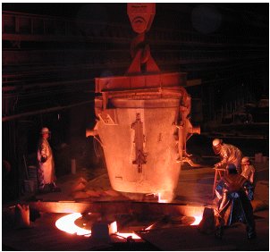
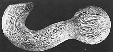
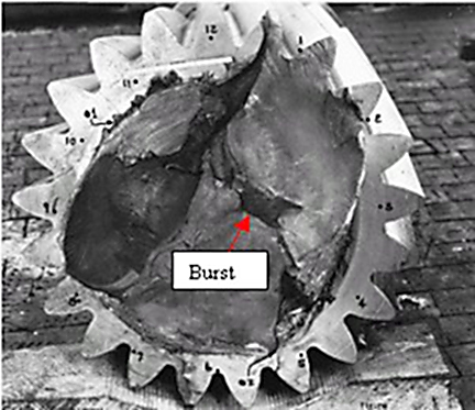
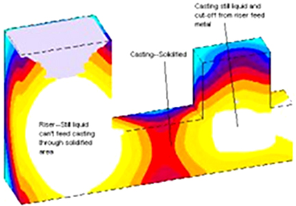
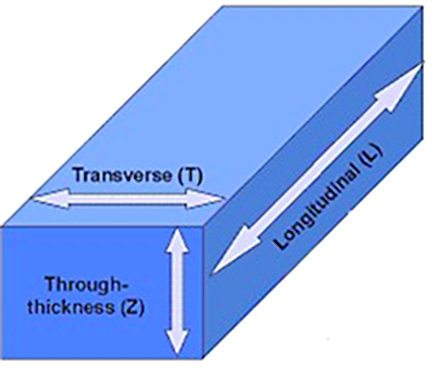
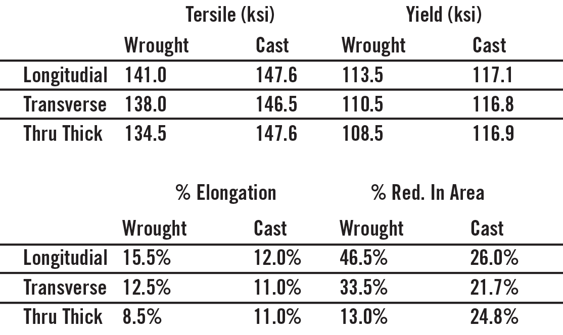
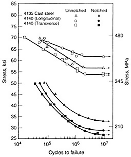
: Passing null to parameter #1 ($string) of type string is deprecated in <b>/home/gearredirontest/public_html/wp-content/themes/Newspaper/loop.php</b> on line <b>52</b><br />")
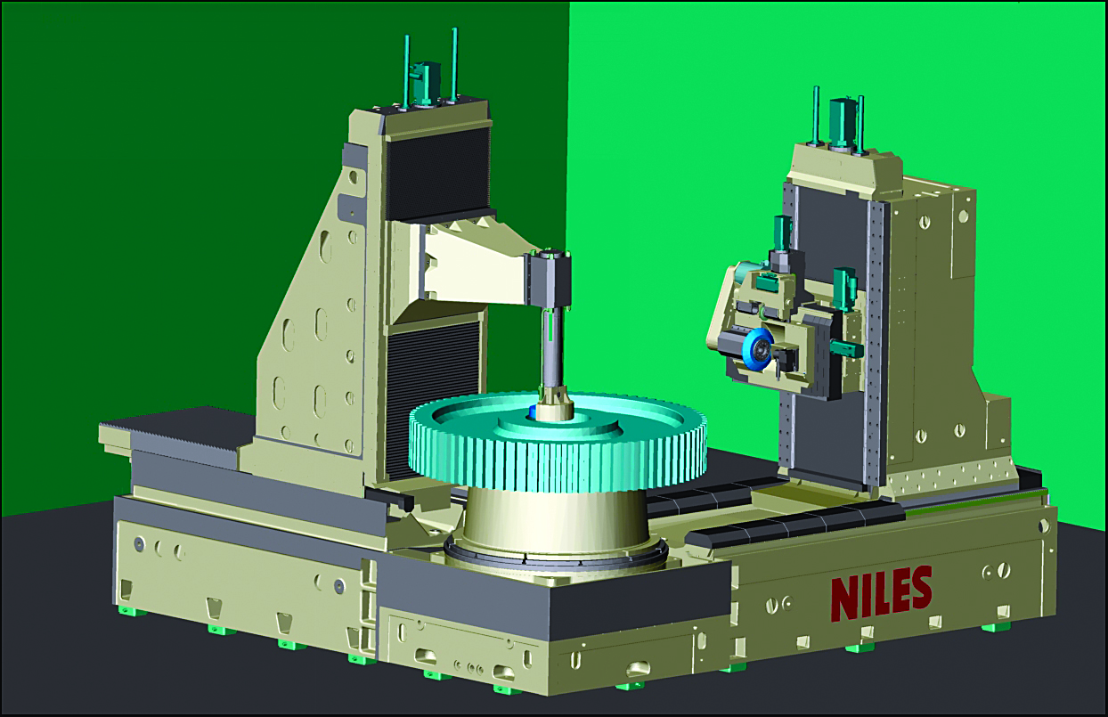
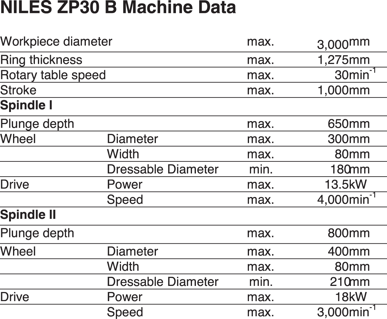
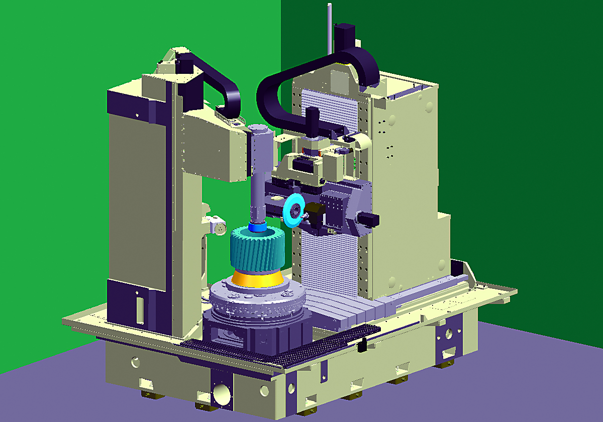
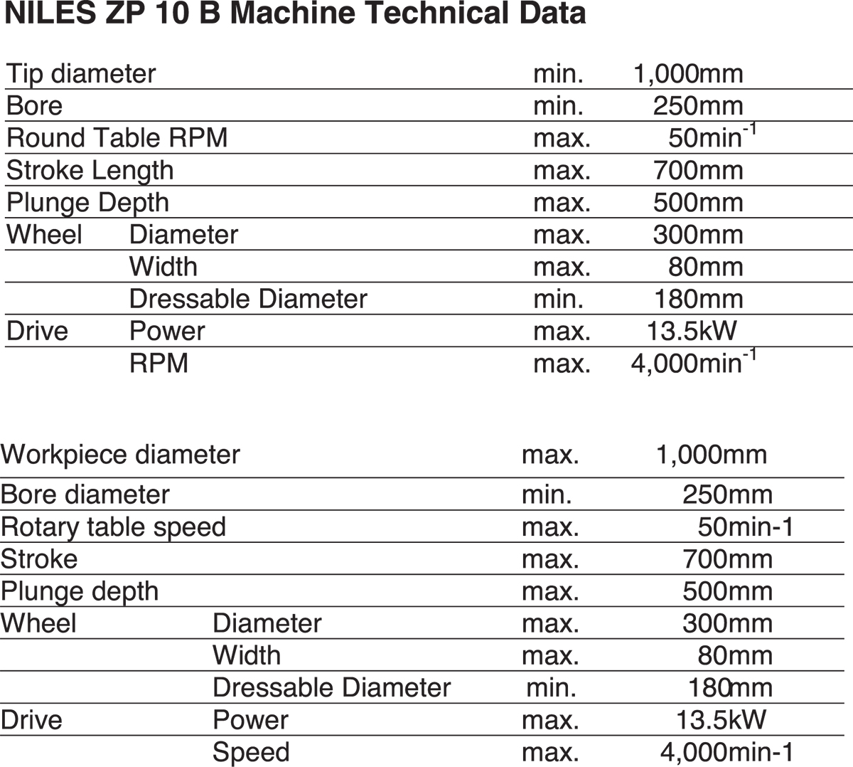
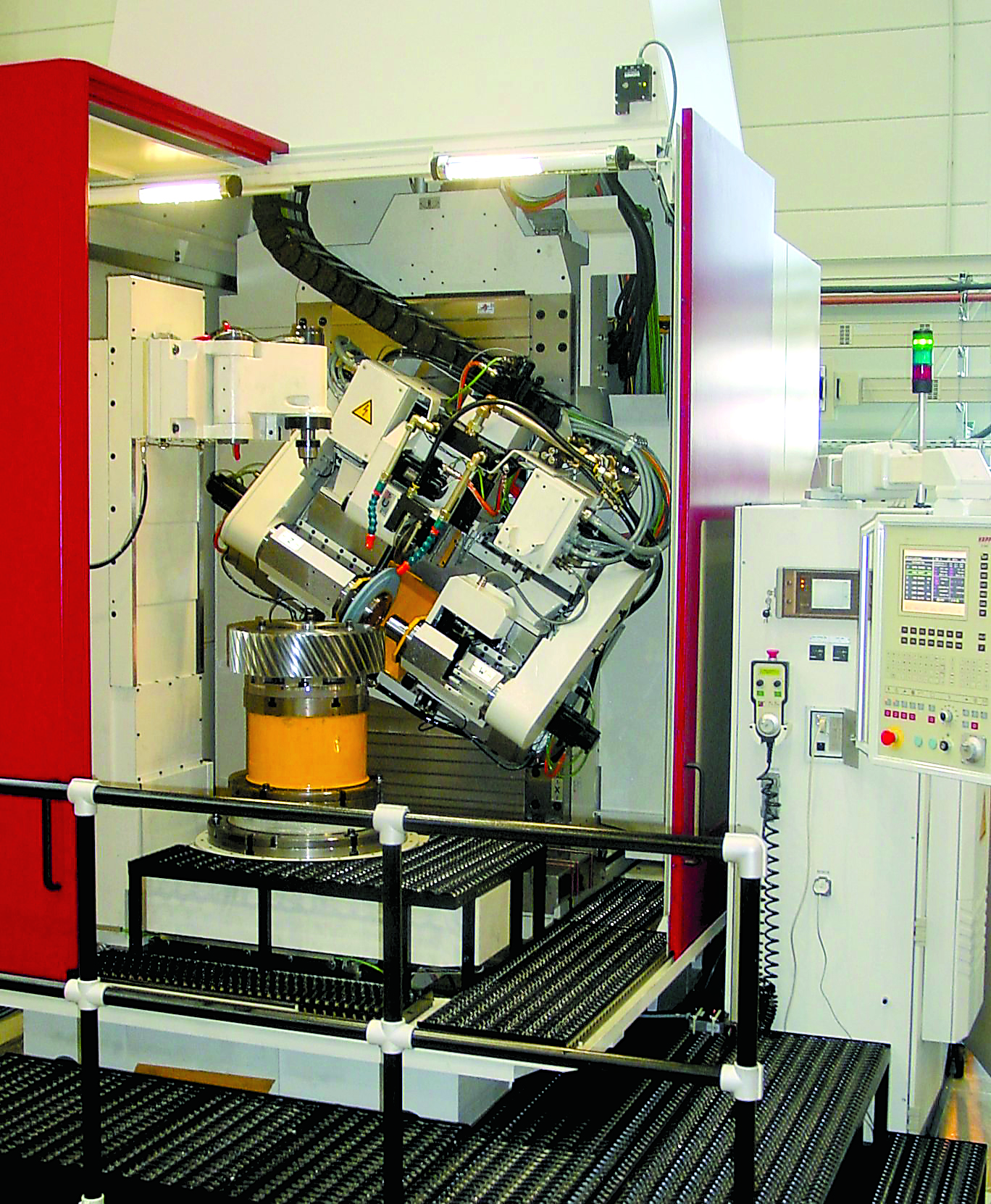
: Passing null to parameter #1 ($string) of type string is deprecated in <b>/home/gearredirontest/public_html/wp-content/themes/Newspaper/loop.php</b> on line <b>52</b><br />")
 Introduction
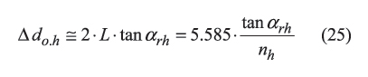
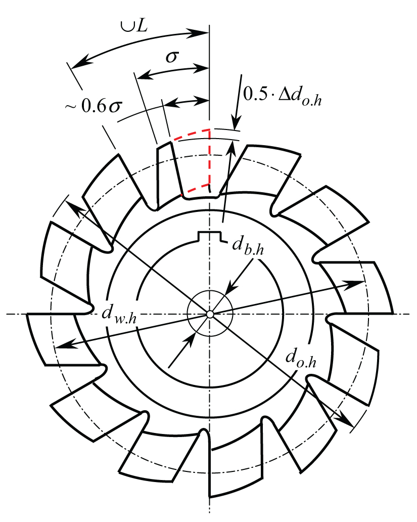
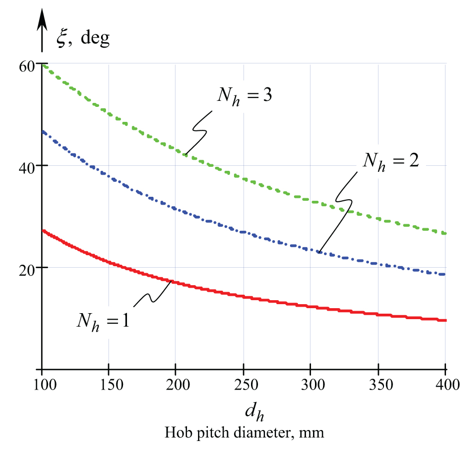
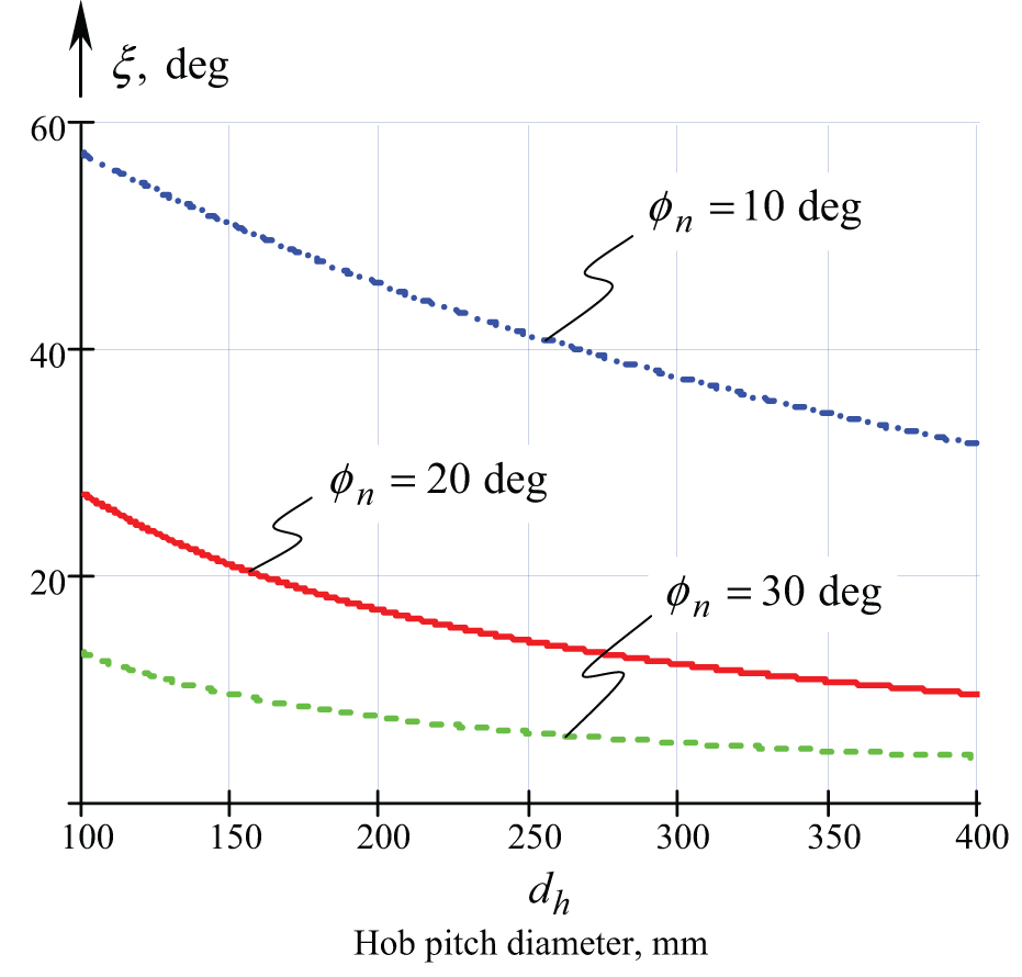
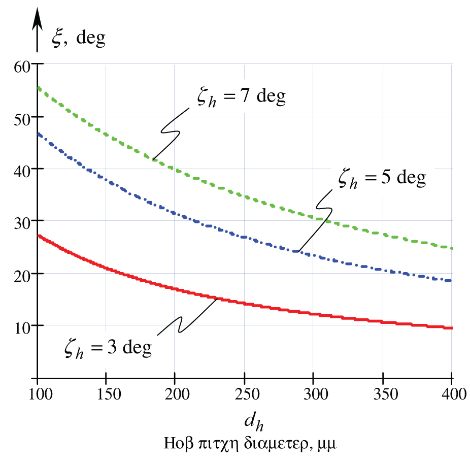
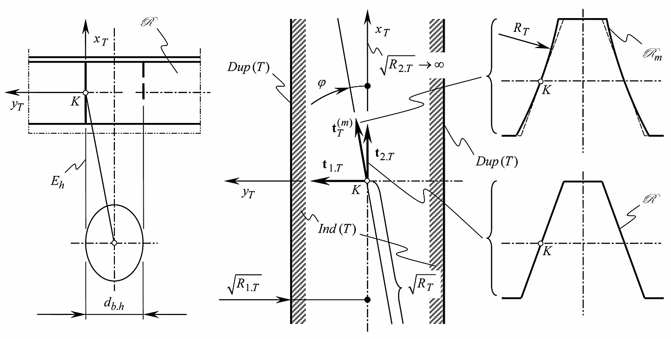

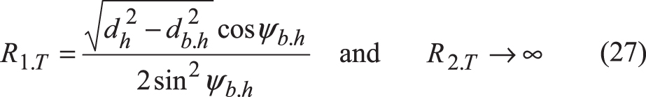
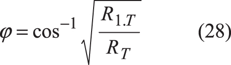

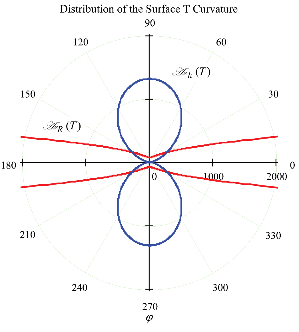

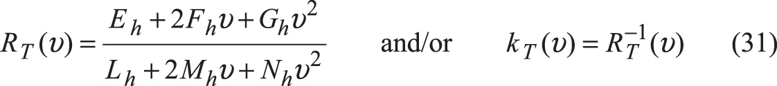
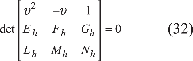
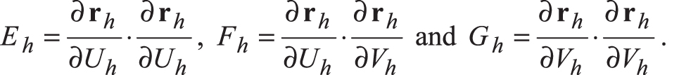 Gaussian coefficients of the second fundamental form Φ 2.T of the machining surface T of the involute hob are designated as Lh , Mh and Nh. They also are functions of the Uh− and Vh− parameters [see Eq. (12)], i.e. Lh=Lh(Uh,Vh), Mh=Mh(Uh,Vh) and Nh=Eh(Uh,Vh). The coefficients Lh , Mh and Nh are derived from Eq. (12) using for this purpose equations:
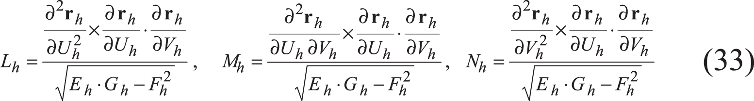
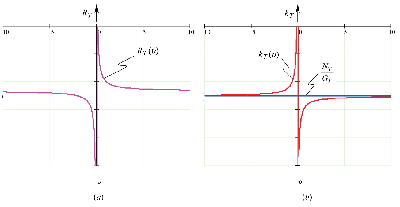
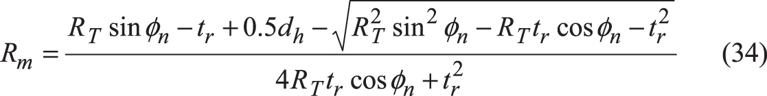 The corresponding equation for the distance dm could be represented in the form
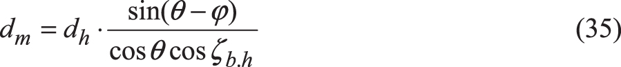 where
where
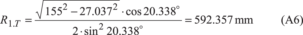 The required value of angle Φ[Eq. (28)]
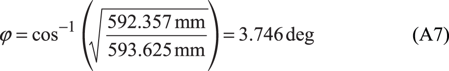
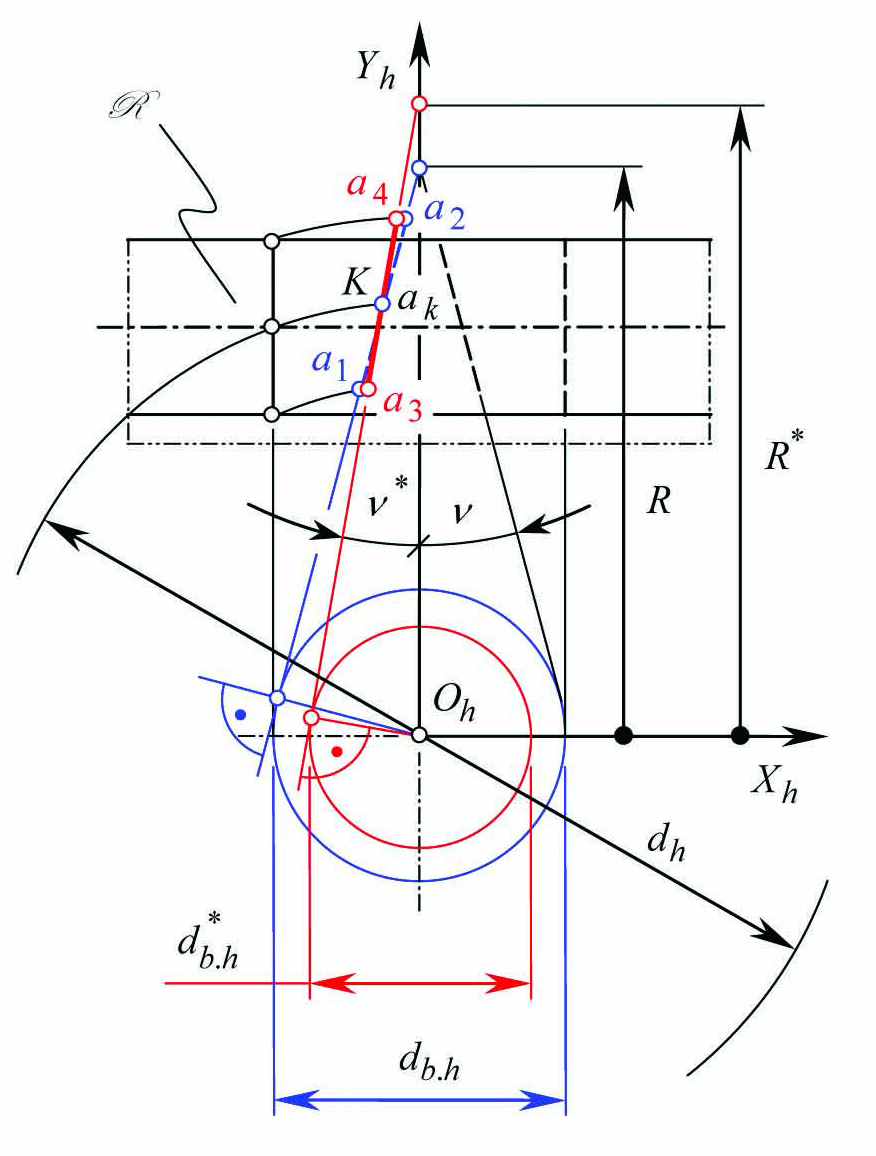

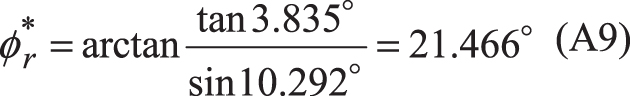
: Passing null to parameter #1 ($string) of type string is deprecated in <b>/home/gearredirontest/public_html/wp-content/themes/Newspaper/loop.php</b> on line <b>52</b><br />")
: Passing null to parameter #1 ($string) of type string is deprecated in <b>/home/gearredirontest/public_html/wp-content/themes/Newspaper/loop.php</b> on line <b>52</b><br />")


